Tooth surface dynamic load distribution calculation method

A technology of distributed calculation and dynamic load, applied in the field of dynamic analysis

Pending Publication Date: 2019-10-11
NORTHWESTERN POLYTECHNICAL UNIV
View PDF0 Cites 6 Cited by
  • Summary
  • Abstract
  • Description
  • Claims
  • Application Information

AI Technical Summary

Problems solved by technology

[0004] At present, there are few methods for coupling analysis of tooth surface transient contact and system vibration considering complex distributed errors, and there is no research method that comprehensively investigates the influence of gear basic parameters, gear accuracy and load torque on the vibration characteristics of gear systems

Method used


Image

  • Tooth surface dynamic load distribution calculation method
  • Tooth surface dynamic load distribution calculation method
  • Tooth surface dynamic load distribution calculation method

Examples


Embodiment Construction

[0019] The following will clearly and completely describe the technical solutions in the embodiments of the present invention with reference to the accompanying drawings in the embodiments of the present invention. Obviously, the described embodiments are only some, not all, embodiments of the present invention. Based on the embodiments of the present invention, all other embodiments obtained by persons of ordinary skill in the art without making creative efforts belong to the protection scope of the present invention.

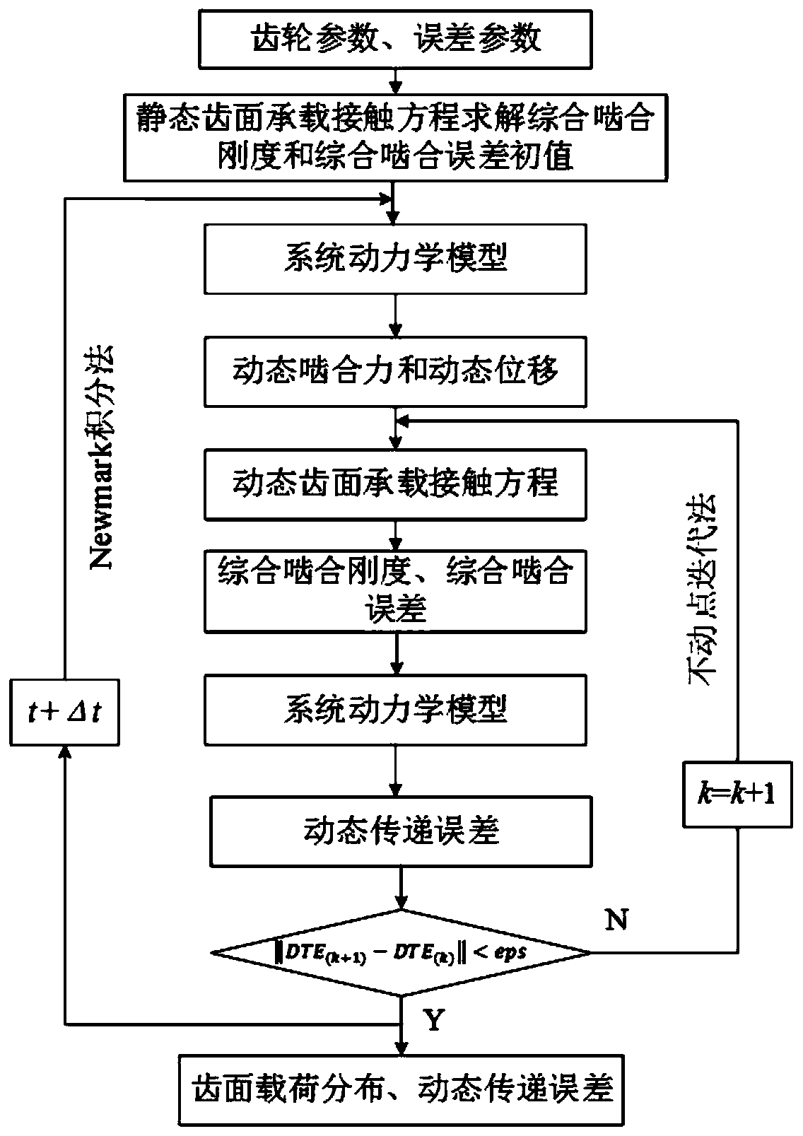
[0020] Such as figure 1 As shown, the tooth surface dynamic load distribution calculation method considering the error provided by the present invention, the specific steps are as follows:

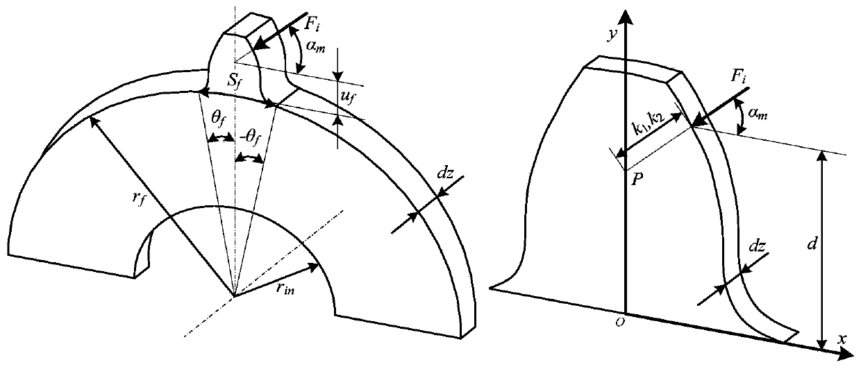
[0021] 1. Parameter input: Determine the gear parameters and error parameters, and substitute them into the static tooth surface bearing contact equation.

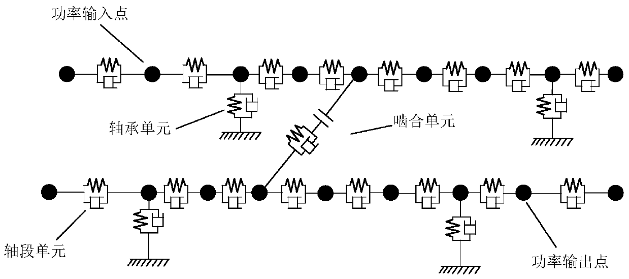
[0022] 2. Initial value calculation: Based on the tooth surface bearing contact analysis method, the driving wheel ...


PUM


Abstract

The invention discloses a tooth surface dynamic load distribution calculation method, relates to the technical field of dynamic analysis, and couples error-considered gear pair meshing stiffness and comprehensive meshing error calculation with system dynamic model solution so as to construct a tooth surface instantaneous contact and system vibration bidirectional feedback coupling dynamic model. ANewmark numerical integration method and a fixed point iteration method are combined to solve the coupling kinetic model, and therefore tooth surface dynamic load distribution considering errors at different rotating speeds is obtained. According to the method, the tooth surface transient contact and system vibration coupling dynamic model is established on the basis of a tooth surface bearing contact analysis method, and a more scientific and reasonable theoretical basis is provided for revealing a nonlinear coupling action mechanism of tooth surface transient contact characteristics and system vibration.

Description

technical field [0001] The invention relates to the technical field of dynamic analysis, in particular to a calculation method for dynamic load distribution on tooth surfaces. Background technique [0002] During the actual operation of the gear system, there are relative vibration displacements of different amplitudes between the meshing tooth surfaces at different speeds, and the vibration displacement will cause differences between the actual contact state of the tooth surfaces and the contact state under quasi-static conditions. When the vibration displacement is large, the tooth surface may even completely disengage. [0003] The difference in the actual contact state of the tooth surface will directly cause the mesh stiffness and comprehensive mesh error of the gear pair to be different from those under quasi-static conditions. The meshing stiffness and comprehensive meshing error of the gear pair determine the strength of the system vibration, and the vibration displ...

Claims


Application Information

Patent Timeline
IPC IPC(8): G06F17/50
CPCG06F30/17G06F30/23G06F2119/06Y02T90/00
Inventor 刘更王海伟刘岚袁冰吴立言龚境一
Owner NORTHWESTERN POLYTECHNICAL UNIV
Why Eureka
Try Eureka