Aperiodic sounding reference signal (SRS) transmission method and terminal equipment
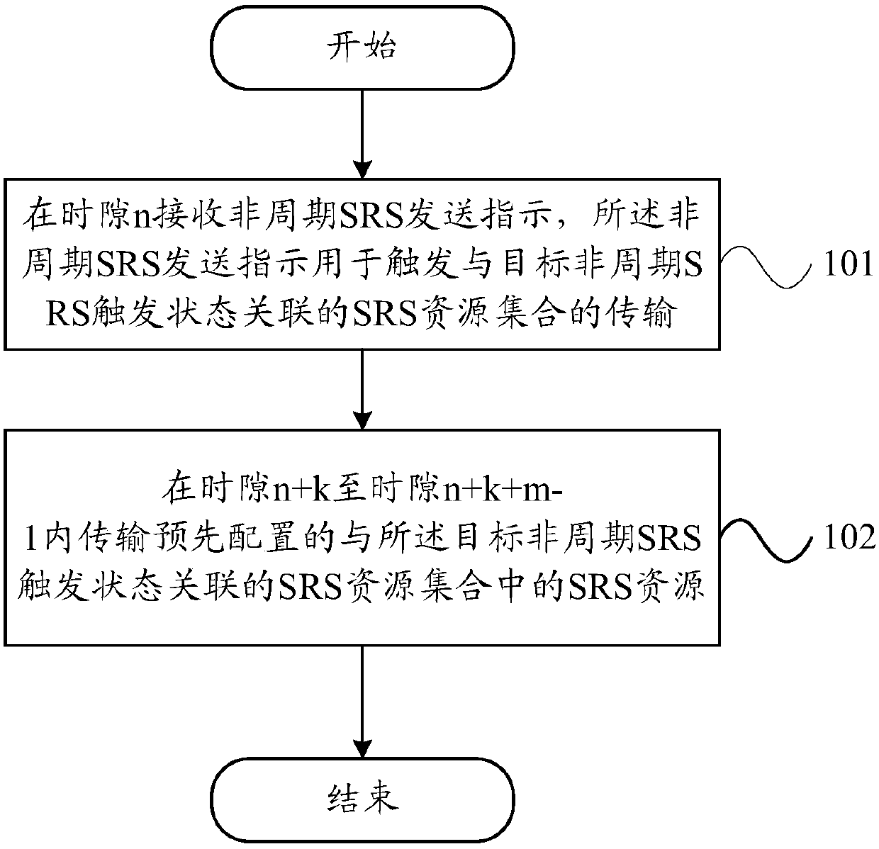
A technology for sounding reference signal and terminal equipment, which is applied in the field of aperiodic sounding reference signal SRS transmission method and terminal equipment, and can solve problems such as transmission failure
- Summary
- Abstract
- Description
- Claims
- Application Information
AI Technical Summary
Problems solved by technology
Method used
Image
Examples
example 1
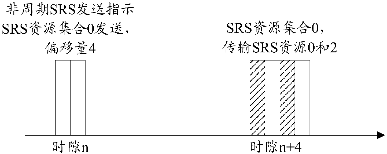
[0053] Such as figure 2 As shown, it is assumed that the aperiodic SRS trigger state 0 is configured by high layer signaling to correspond to the SRS resource set 0, the SRS resource set 0 includes SRS resources 0-3, and the offset of the aperiodic SRS transmission indication is 4. When the terminal device receives the aperiodic SRS trigger state 0 transmission triggered by the downlink control information in time slot n, the terminal will start to send SRS resource set 0 in time slot n+4. Due to the influence of the time slot format and network side configuration, a maximum of 2 SRS resources can be sent in time slot n+k. Therefore, SRS resource 0 and SRS resource 2 are transmitted in time slot n+4, while SRS resource 1 and SRS resource 3 will no longer be transmitted.
[0054] On the other hand, when m is greater than or equal to 2, in this case, the terminal transmits all or part of the SRS resources in the SRS resource set from slot n+k to slot n+k+m-1.
[0055] Specifi...
example 2
[0060] Example 2 (m is equal to 2):
[0061] Such as image 3 As shown, it is assumed that the aperiodic SRS trigger state 0 is configured by high layer signaling to correspond to the SRS resource set 0, the SRS resource set 0 includes SRS resources 0-3, and the offset of the aperiodic SRS transmission indication is 4. When the terminal device receives the aperiodic SRS trigger state 0 transmission triggered by the downlink control information in time slot n, the terminal will start to send SRS resource set 0 in time slot n+4. Due to the influence of time slot configuration, a maximum of 2 SRS resources can be sent in a time slot, therefore, SRS resource 0 and SRS resource 2 are transmitted preferentially in time slot n+4, and SRS resource 1 is transmitted in time slot n+5 and SRS resources3.
[0062] Although transmitting the same number of SRS resources in each time slot can simplify the implementation complexity of the base station, it also has restrictions on the configu...
example 3
[0063] Example three (m is equal to 3):
[0064] Such as Figure 4 As shown, it is assumed that the aperiodic SRS trigger state 0 is configured by high layer signaling to correspond to the SRS resource set 0, the SRS resource set 0 includes SRS resources 0-3, and the offset of the aperiodic SRS transmission indication is 4. When the terminal receives the aperiodic SRS trigger state 0 transmission triggered by the downlink control information in time slot n, the terminal will start to send SRS resource set 0 in time slot n+4. Due to the influence of the time slot format and network side configuration, a maximum of 3 SRS resources can be sent in the n+4 time slot, no SRS resource is configured in the n+5 time slot, and a maximum of 1 SRS resource can be sent in the n+6 time slot. Therefore, SRS resources 0, 1 and 2 are preferentially transmitted in time slot n+4, and SRS resource 3 is transmitted in time slot n+6.
[0065] Further, in the above-mentioned embodiments of the pre...
PUM
 Abstract
Description
Claims
Application Information
 - R&D
- Intellectual Property
- Life Sciences
- Materials
- Tech Scout
- Unparalleled Data Quality
- Higher Quality Content
- 60% Fewer Hallucinations
Browse by: Latest US Patents, China's latest patents, Technical Efficacy Thesaurus, Application Domain, Technology Topic, Popular Technical Reports.
© 2025 PatSnap. All rights reserved.Legal|Privacy policy|Modern Slavery Act Transparency Statement|Sitemap|About US| Contact US: help@patsnap.com


