Interbody fusion cage driver

An intervertebral fusion cage and driver technology, applied in joint implants, joint implants, spinal implants, etc., can solve the problems of increasing the risk of loosening of the cage, increasing the torque value, etc., and reducing the Risk of loosening, time cost saving, effect of shortening operation time

Pending Publication Date: 2019-10-15
TIANJIN ZHENGTIAN MEDICAL INSTR CO LTD
View PDF0 Cites 3 Cited by
  • Summary
  • Abstract
  • Description
  • Claims
  • Application Information

AI Technical Summary

Problems solved by technology

However, when the thread is unscrewed in the opposite direction, the cage will be subjected to a slight torque. When the thread fits tightly, the torque value will increase, increasing the risk of cage loosening

Method used


Image

  • Interbody fusion cage driver
  • Interbody fusion cage driver
  • Interbody fusion cage driver

Examples


Embodiment 1

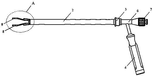
[0042] An intervertebral fusion device driver, the intervertebral fusion device driver comprising:

[0043] A clamping structure for clamping the intervertebral fusion device, including a connecting part and a clamping piece connected to one end of the connecting part;

[0044] A force-applying structure for applying force to the clamping part so that the clamping part is force-clamped;

[0045] The connection part is connected with the force applying structure.

[0046] The using method of described intervertebral fusion device injector, comprises the steps:

[0047] Position the clamping part on the intervertebral fusion device, the operator applies force to the force-applying structure, and then the force-applying structure applies force to the clamping part, the clamping part is tightened, clamps the intervertebral fusion device, and the intervertebral fusion device is After being placed in the desired position, the force applied to the force-applying structure is remove...

Embodiment approach

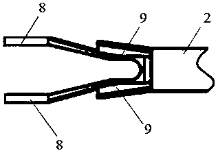
[0068] As another embodiment, the clamping member 8 can also be an open elastic piece;

[0069] As a preferred embodiment, the clamping member and the rod body are integrally structured;

[0070] The material of the clip and the clamping plate can be metal or plastic, which needs to have certain elasticity, can be tightened when stressed, and can restore the original shape after the external force is removed;

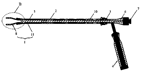
[0071] The clamping rod 1 and the sleeve 2 are slidingly fitted, and the elastic member is connected in the middle, so that the two clamping pieces 8 can be closed and opened after the structure is stressed;

[0072] The intervertebral fusion driver also includes a stop nut 3, a positioning part 6, and a tail cap 7 that are arranged on the other end of the rod body 11, and the distance between the tail cap 7 and the clamping member 8 is relatively long;

[0073] The limit nut 3 is threadedly connected with the sleeve pipe 2, and both the limit nut 3 and the sleeve pipe...


PUM


Abstract

The invention provides an interbody fusion cage driver. The interbody fusion cage driver comprises a clamping structure and a force applying structure, wherein the clamping structure is used for clamping an interbody fusion cage and comprises a connecting part and a clamping element connected to one end of the connecting part; the force applying structure is used for applying force to the clampingelement to enable the clamping element to perform clamping under the force; and the connecting part is connected with the force applying structure. The interbody fusion cage driver is simple in structure, and the condition that fixation and screwing-out structures of the interbody fusion cage are realized by threads during traditional implantation of the interbody fusion cage is avoided; in the whole interbody fusion operation, the interbody fusion cage does not receive torsion action; the risk of looseness of the implanted interbody fusion cage is reduced; the interbody fusion cage driver has high universality and can realize clamping and loosening effects on multiple interbody fusion cages; and the functions of clamping and loosening the interbody fusion cages can be realized quickly, the time cost for screwing in and out of threads is saved, and the operation time is shortened.

Description

technical field [0001] The invention belongs to the technical field of surgical instruments, and relates to an intervertebral fusion device driver. Background technique [0002] In intervertebral fusion surgery, an intervertebral fusion cage is held by a driver and implanted into the human spine. The prior art usually adopts a screwdriver with a head. Firstly, the fusion device is screwed into the head thread structure of the driver, and then after the fusion device is implanted into the human body, the thread is unscrewed in the opposite direction, and the driver is removed, and the implantation is completed. However, when the thread is unscrewed in the opposite direction, the fusion cage will be subjected to a slight torque. When the thread fits tightly, the torque value will increase, which increases the risk of the cage loosening. [0003] Therefore, there is an urgent need in the art to provide an intervertebral fusion device driver to simplify the insertion process o...

Claims


Application Information

Patent Timeline
Patent Type & Authority Applications(China)
IPC IPC(8): A61F2/46A61F2/44
CPCA61F2/4611A61F2/4455A61F2002/4622A61F2/4603
Inventor 邢学超陈旭鲍野
Owner TIANJIN ZHENGTIAN MEDICAL INSTR CO LTD
Why Eureka
Try Eureka