Power electronic transformer system, transformer and fault ride-through control method thereof

A technology for power electronics and transformers, applied in the field of bidirectional isolated DC voltage conversion, can solve the problems of reduced reliability and stability of the power grid, system shutdown, etc., and achieve the effect of improving reliability and stability

Active Publication Date: 2021-09-03
XJ ELECTRIC +2
View PDF4 Cites 0 Cited by
  • Summary
  • Abstract
  • Description
  • Claims
  • Application Information

AI Technical Summary

Problems solved by technology

[0003] The purpose of the present invention is to provide a power electronic transformer, which is used to solve the problem of providing execution hardware for the power electronic transformer with fault ride-through capability;
[0004] A fault ride-through control method for power electronic transformers is also proposed, which is used to solve the problem that when a short-circuit fault occurs in the DC power grid on the high-voltage side (referring to the DC power grid connected to the high-voltage side of the power electronic transformer), the power electronic transformer in the prior art fails and the system shuts down. Causes the problem of reduced reliability and stability of power grid operation;
[0005] And another fault ride-through control method for power electronic transformers, which is used to solve the problem that when a short-circuit fault occurs in the low-voltage side DC power grid (referring to the DC power grid connected to the low-voltage side of the power electronic transformer), the power electronic transformer in the prior art fails, that is, the system shuts down, Causes the problem of reduced reliability and stability of power grid operation;
[0006] A power electronic transformer system is also proposed, which is used to solve the problem that the power electronic transformer in the prior art fails, that is, the system shuts down, which causes the reliability and stability of the power grid to decrease.

Method used


Image

  • Power electronic transformer system, transformer and fault ride-through control method thereof
  • Power electronic transformer system, transformer and fault ride-through control method thereof
  • Power electronic transformer system, transformer and fault ride-through control method thereof

Examples


Embodiment Construction

[0049] The specific embodiments of the present invention will be further described below in conjunction with the accompanying drawings.

[0050] Transformer system embodiment:

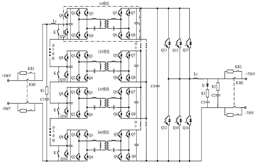
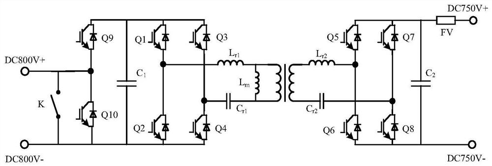
[0051] This implementation proposes a power electronic transformer system, including a power electronic transformer, and a controller that controls and connects the switching tubes in the power electronic transformer, such as figure 1 In the power electronic transformer shown, the high-voltage side and low-voltage side have specific voltage levels, which are ±10kV (or 20kV) and 750V respectively, and the total power of the system is 1.5MW. In order to meet the requirements of the voltage level, the power electronic transformer includes 24 modules (1# module, ..., 24# module) connected between the high-voltage side and the low-voltage side of the DC grid, and two redundant standby module, not shown in the figure), the high-voltage side of each module is connected in series, and the low-voltage side is ...


PUM


Abstract

The invention relates to a power electronic transformer system, a transformer and a fault ride-through control method thereof, and belongs to the technical field of bidirectional isolated DC voltage conversion. The power electronic transformer includes: at least one module, and each module includes a high-voltage half-bridge module and a bidirectional DC conversion unit. The high-voltage half-bridge module includes a high-voltage upper arm branch and a high-voltage lower arm branch; it also includes a self-blocking module, which is connected in parallel with the low-voltage side of each module. The self-blocking module includes a low-voltage half-bridge module, and the low-voltage half-bridge module includes a low-voltage upper arm. The branch circuit and the low-voltage lower arm branch circuit, the low-voltage lower arm branch circuit is used to connect the low-voltage side DC power grid, and the general branch circuit formed by connecting the low-voltage upper arm branch circuit and the low-voltage lower arm branch circuit is connected in parallel with the low-voltage side of each module. Through the coordinated control of the half-bridge module provided on the high-voltage side of the module and the half-bridge module in the self-blocking module, the power electronic transformer of the present invention has fault ride-through capability, which improves the reliability and stability of power grid operation.

Description

technical field [0001] The invention belongs to the technical field of bidirectional isolated DC voltage conversion, and in particular relates to a power electronic transformer system, a transformer and a fault ride-through control method thereof. Background technique [0002] At present, power electronic transformers used in DC distribution network, new energy grid connection and energy Internet have many advantages, such as: reduced weight and volume; precise and controllable voltage and current, improved power quality; modular design, easy for system expansion, Disassembly and maintenance; it has the advantages of low pollution, high efficiency and intelligence. However, when the power electronic transformer fails, the entire system where the power electronic transformer is located will fail and shut down, which will seriously affect the reliability and stability of the DC distribution network power supply. Contents of the invention [0003] The purpose of the present ...

Claims


Application Information

Patent Timeline
Patent Type & Authority Patents(China)
IPC IPC(8): H02M3/335H02M1/32H02M1/36H02M1/14H02H7/12
CPCH02H7/1213H02M1/14H02M1/32H02M1/36H02M3/3353H02M1/007H02M1/325Y02B70/10
Inventor 曹建博黄辉安昱王林牛化鹏吴金龙辛德锋黎阳郜亚秋肖飞陈雪龚培娇赵建荣
Owner XJ ELECTRIC
Why Eureka
Try Eureka