
Shearing part, transmission part, shearing assembly and door and window structure

A technology for transmission parts and doors and windows, applied in the field of doors and windows, can solve the problems affecting the installation efficiency of door and window installation parts, affecting the installation and adjustment efficiency of doors and windows, and falling out of door and window installation parts, so as to achieve convenient installation and adjustment, convenient installation and removal of installation parts, and simplified The effect of the installation operation

Pending Publication Date: 2019-10-18
SHENZHEN HOPO WINDOW CONTROL TECH CO LTD
View PDF0 Cites 0 Cited by
  • Summary
  • Abstract
  • Description
  • Claims
  • Application Information

AI Technical Summary

Problems solved by technology

Although the operational feasibility and speed of this installation method have been improved to a certain extent, it has limitations during installation. When changing the length of the transmission part, the accessories of the transmission part must be removed first, and unnecessary transmission parts should be cut off. Install the connection of hardware accessories in the reserved card slot
Therefore, this technical solution is very cumbersome to operate when changing the length of the transmission part, which seriously affects the installation efficiency of the door and window installation parts, thereby affecting the installation and adjustment efficiency of the entire door and window
[0004] In addition, in the prior art, the connection reliability between the door and window installation parts and the transmission part is relatively low, and the door and window installation parts are easy to come off from the transmission part

Method used


Image

  • Shearing part, transmission part, shearing assembly and door and window structure
  • Shearing part, transmission part, shearing assembly and door and window structure
  • Shearing part, transmission part, shearing assembly and door and window structure

Examples


Embodiment 1

[0081] Refer below Figure 11-Figure 12 A shear assembly of a specific embodiment of the invention is described.

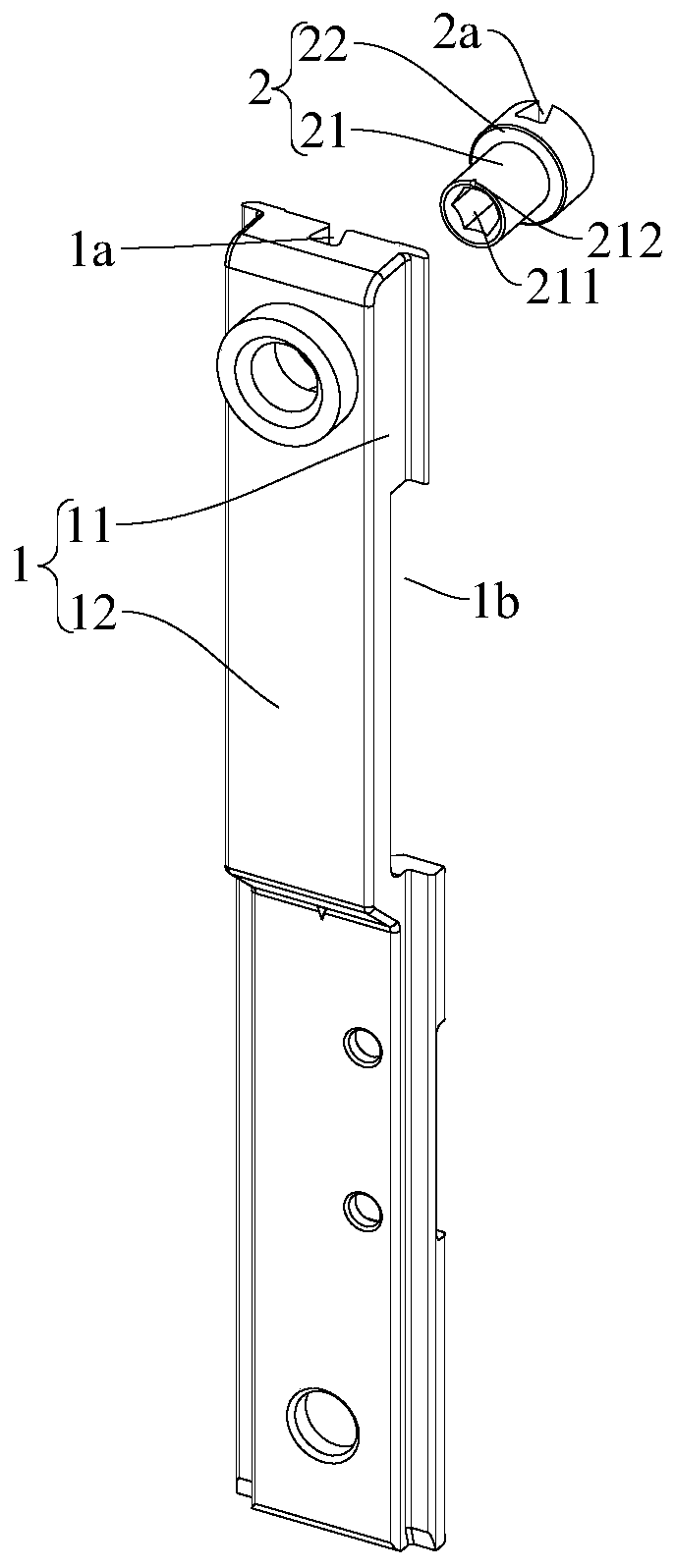
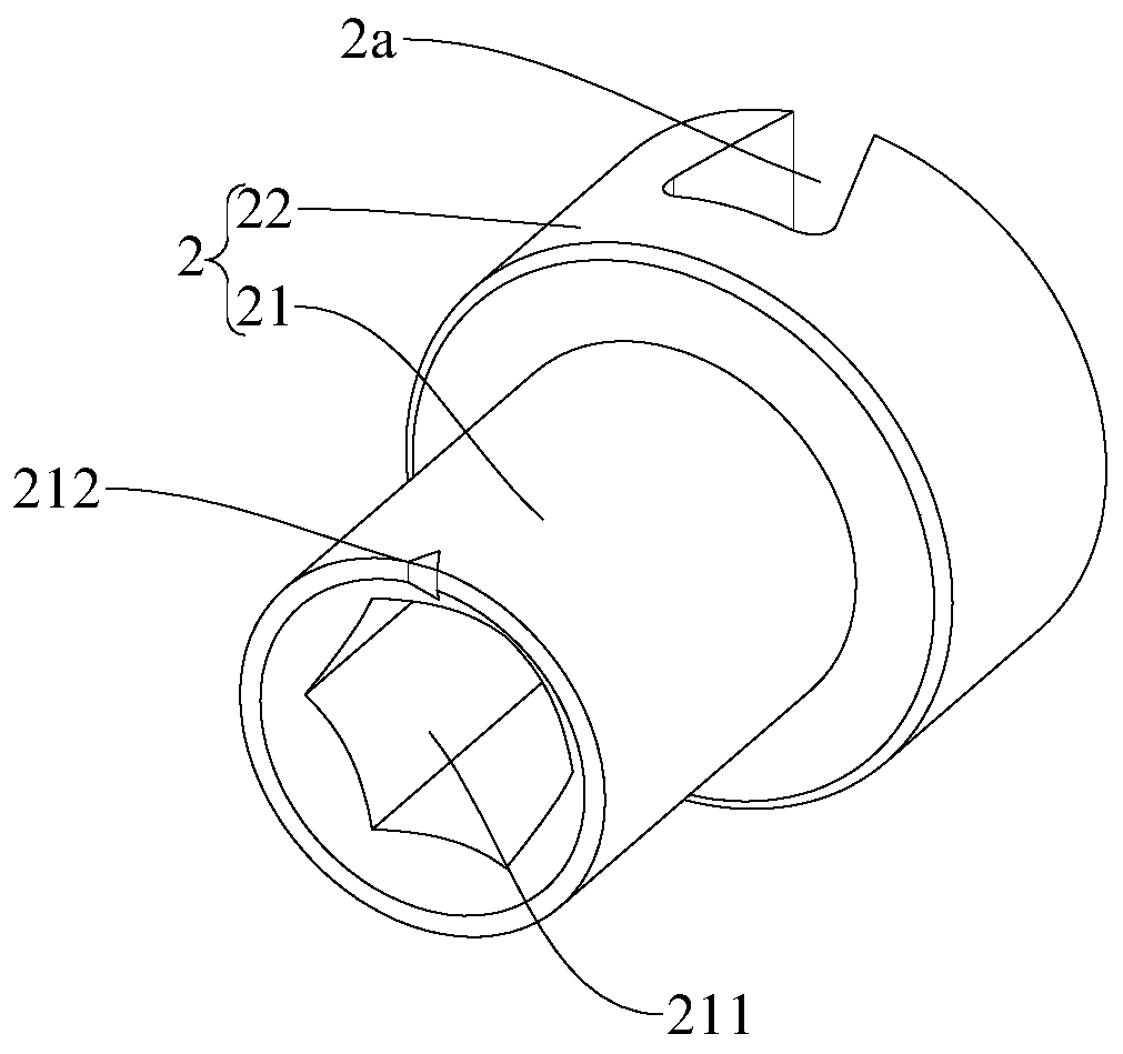
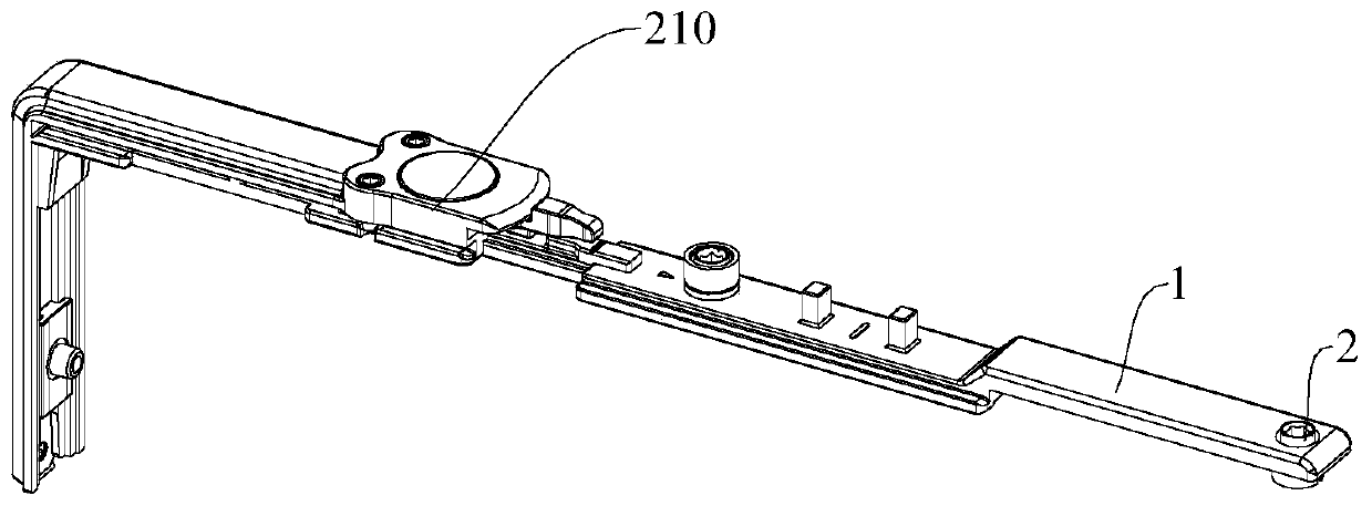
[0082] like Figure 11-Figure 12 As shown, the shearing assembly in this embodiment includes a shearing element and a transmission element 100 connected with the shearing element. The shearing piece includes a mounting piece 1 and a shearing piece 2. The mounting piece 1 is provided with a matching groove 1a and an adjusting groove 1b. The matching groove 1a is opened downwards, and the width of the matching groove 1a is in the upward direction. Gradually increasing, the matching groove 1a is suitable to be connected with the matching protrusion 100a on the transmission part 100, and one end of the transmission part 100 can extend into the adjustment groove 1b to adjust the relative position of the mounting part 1 and the transmission part 100, cut The block 2 is rotatably arranged on the mounting part 1. The shear block 2 is provided with a shear groove 2a conn...

Embodiment 2

[0084] like Figure 13-Figure 14 As shown, the structure of the shearing assembly in this embodiment is substantially the same as that of the shearing assembly in Embodiment 1. The difference is that the transmission member 100 is provided with limiting grooves on both sides of the mating protrusion 100a 100b, the mounting part 1 is provided with a limiting structure that cooperates with the limiting groove 100b. In this way, the phenomenon that the transmission part 100 is detached from the mounting part 1 can be better avoided.

Embodiment 3

[0086] like Figure 15 As shown, the structure of the cutout block 2 of this embodiment is the same as that of Embodiment 1. As shown in the figure, the mounting part 1 of this embodiment includes a sliding section, and the shearing block 2 is rotatably fitted on the sliding section. The transmission part 100 includes an adjustment section 110 and a connection section 120. The adjustment section 110 is provided with a matching protrusion 100a. The cross section of the cooperation protrusion 100a is a rectangle. The connection section 120 is connected to the end of the adjustment section 110 away from the mounting part 1. 120 is suitable for being connected with other hardware structures.

[0087] The door and window structure of the present invention includes a profile piece and the aforementioned shearing assembly, and the shearing assembly is installed on the profile piece. The door and window assembly of the present invention includes the above-mentioned shearing assembly...


PUM


Abstract

The invention discloses a shearing part, a transmission part, a shearing assembly and a door and window structure. The shearing part comprises a mounting part and a shearing block. The shearing blockis rotationally arranged on the mounting part, is used for being connected with the transmission part, and is provided with a shearing groove. The shearing groove is matched with the transmission part. When the shearing block and the transmission part rotate relative to each other, the shearing groove is used for cutting a structure, for accommodating the transmission part, of the shearing groove.The shearing part can be quickly mounted on the transmission part, and the position of the shearing part and the position of the transmission part can be conveniently adjusted.

Description

technical field [0001] The invention relates to the technical field of doors and windows, in particular to a shearing member, a transmission member, a shearing assembly and a door and window structure. Background technique [0002] The connection and installation between the door and window hardware and the transmission parts in the prior art adopts the punching connection installation of the transmission part. Since the transmission parts between the hardware and the hardware need to be accurately calculated to obtain the length dimension, after cutting the transmission part with a suitable size , and then punch out connection holes at specific positions to realize the connection between various hardware components. However, this installation method is cumbersome to operate, and if there is an error in punching, it is necessary to re-cut the transmission part of appropriate size, and to re-cut the transmission part needs to remove the hardware accessories. This process is v...

Claims


Application Information

Patent Timeline
Patent Type & Authority Applications(China)
IPC IPC(8): E05F7/00
CPCE05F7/00
Inventor 刘治国玉冬丽
Owner SHENZHEN HOPO WINDOW CONTROL TECH CO LTD
Learn More