
Oil pipe fixing device

A technology for fixing devices and oil pipes, applied in the direction of pipe components, pipe supports, delivery pipes/joints, etc., can solve the problems of short continuous working time of refueling personnel, increase the construction period, and affect the construction progress, so as to shorten the maintenance time and reduce the Working time and the effect of reducing the number of people

Inactive Publication Date: 2019-10-18
MCC BAOSTEEL TECH SERVICE
View PDF12 Cites 0 Cited by
  • Summary
  • Abstract
  • Description
  • Claims
  • Application Information

AI Technical Summary

Problems solved by technology

[0002] In the process of iron and steel production, the amount of periodic refueling of the roller bearings of each unit is huge, especially in high temperature seasons, the temperature of the bearings is high, and the frequency of roller refueling increases. Influence, in the past, three workers were required to refuel, one person held the refueling pipe to refuel, one person operated the oil pump, and another person was responsible for transmitting the start and stop signals of refueling (because the motor was blocked, the personnel who operated the oil pump could not see the refueling personnel in the transmission most of the time. refueling position on the side)
[0003] The refueling personnel need to hold the refueling pipe to endure the high temperature from the furnace wall. It is measured that the distance from the furnace wall is about 60 degrees Celsius within 0.8 meters. The continuous working time is very short, and the three people need to take turns to rest continuously, which increases the construction period and affects the construction progress

Method used


Image

  • Oil pipe fixing device
  • Oil pipe fixing device
  • Oil pipe fixing device

Examples


Embodiment Construction

[0036] The embodiments of the present invention are described below through specific specific examples, and those skilled in the art can easily understand other advantages and effects of the present invention from the contents disclosed in this specification. The present invention can also be implemented or applied through other different specific embodiments, and various details in this specification can also be modified or changed based on different viewpoints and applications without departing from the spirit of the present invention.

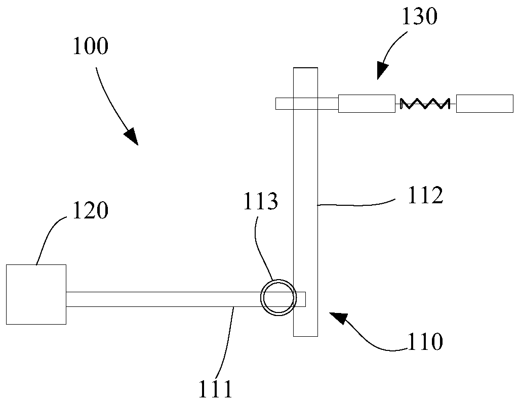
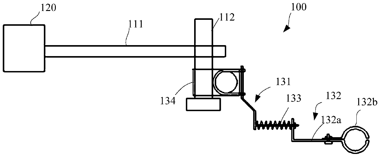
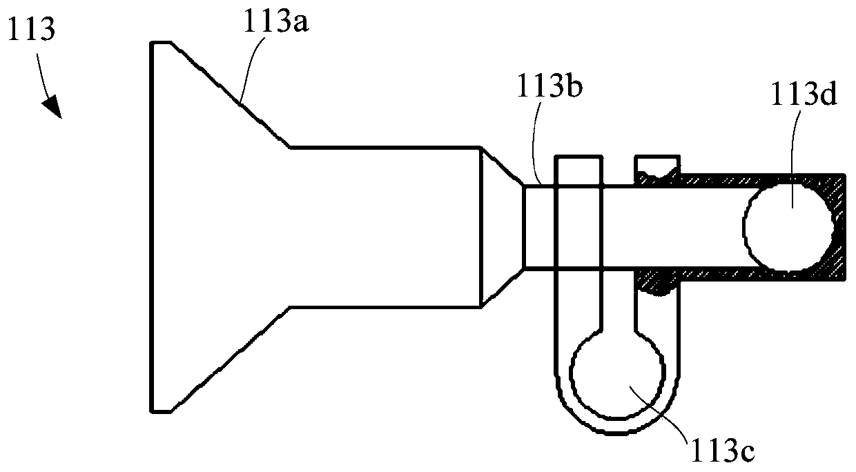
[0037] see Figure 1-5 , It should be noted that the diagrams provided in this embodiment are only schematically illustrating the basic idea of ​​the present invention, and only the components related to the present invention are shown in the diagrams rather than the number and shape of components in actual implementation. and size drawing, the type, quantity and proportion of each component can be changed arbitrarily during actual implement...


PUM


Abstract

The invention provides an oil pipe fixing device. A body, a magnetic force meter base and a fixing unit are included. The body comprises a first straight rod and a second straight rod which are connected. The magnetic force meter base comprises a bolt and is connected with the first straight rod. The fixing unit is connected with the second straight rod and comprises an elastic component, and thefixing unit is used for fixing an oil pipe. The provided oil pipe fixing device is reasonable in design, simple in structure and high in work efficiency.

Description

technical field [0001] The invention relates to the field of metallurgical equipment, in particular to an oil pipe fixing device. Background technique [0002] In the process of iron and steel production, the amount of periodic refueling of the roller bearings of each unit is huge, especially in high temperature seasons, the temperature of the bearings is high, and the frequency of roller refueling increases. Influence, in the past, three workers were required to refuel, one person held the refueling pipe to refuel, one person operated the oil pump, and another person was responsible for transmitting the start and stop signals of refueling (because the motor was blocked, the personnel who operated the oil pump could not see the refueling personnel in the transmission most of the time. refueling position on the side). [0003] The refueling personnel need to hold the refueling pipe to endure the high temperature from the furnace wall. It is measured that the distance from th...

Claims


Application Information

Patent Timeline
IPC IPC(8): F16L3/16F16L3/205F16L55/035F16N21/00
CPCF16L3/16F16L3/205F16L55/035F16N21/00
Inventor 刘弋可王立波施金辉胥菊英石慧卿李连伟
Owner MCC BAOSTEEL TECH SERVICE
Learn More