Automatic channel steel galvanizing device

A driving device and channel steel technology, which is applied in the field of galvanizing device and channel steel galvanizing device, can solve the problems of low production efficiency, burrs on the tail, threats to the personal safety of operators, etc., and achieve the effect of improving production efficiency.

Pending Publication Date: 2019-10-22
JIANGSU GUOQIANG ZINC PLATING IND
View PDF0 Cites 3 Cited by
  • Summary
  • Abstract
  • Description
  • Claims
  • Application Information

AI Technical Summary

Problems solved by technology

At present, the channel steel galvanizing method used in the industry is manual operation. After drying the channel steel with the drying chain, it is conveyed by the second chain to put 4-5 channel steel into the galvanizing pot for galvanizing. When the time is up, an operator lifts one end of several channel steels, starts the drying motor switch at the same time, and then lowers several 4-5 pieces of galvanizing, and another operator in front of the furnace clamps one end of the channel steel, pulls out and adjusts at the same time The direction of the notch is placed on the lead-in magnetic roller table, and the lead-in roller leads the channel steel out of the zinc pot, continuously pulls the channel steel out, and blows off the residual zinc through the air knife. This method requires a lot of manpower, and is manually At the same time as the operation, there will be continuous splashing of zinc liquid, which poses a threat to the personal safety of the operator, and it is also difficult to accurately control the galvanizing time and the number of plated pieces by manual operation, which may easily cause the plated parts to be missed or plated. The zinc layer is uneven and there are burrs on the tail, the quality of galvanizing and appearance of channel steel cannot be guaranteed, and the production efficiency is also low

Method used


Image

  • Automatic channel steel galvanizing device
  • Automatic channel steel galvanizing device

Examples


Embodiment Construction

[0022] The structure and operating principle of the channel steel hot-dip galvanizing device provided by the present invention will be further described in detail below in conjunction with the accompanying drawings.

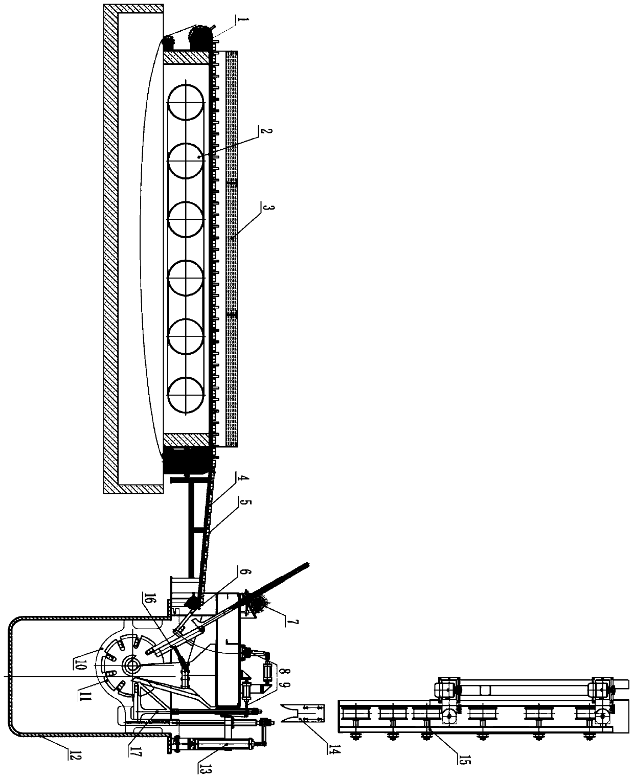
[0023] As shown in Figure 1, it is a schematic structural view of the channel steel hot-dip galvanizing device provided by the present invention. This automatic channel steel galvanizing device comprises input device, zinc pot, output device, and described input device sends channel steel 5 into zinc pot 12, and described output device sends channel steel 5 that galvanizes in zinc pot 12 into The next galvanizing process.

[0024] The zinc pot 12 is provided with a rotatable toothed plate 11, and the rotating shaft of the toothed plate rotating in the zinc pot is provided with an arc-shaped material supporting guide rail 10 coaxial with the rotating shaft. The diameter is smaller than the diameter of the teeth of the toothed disc. One end of the arc of the guide...


PUM


Abstract

The invention discloses an automatic channel steel galvanizing device. The automatic channel steel galvanizing device comprises an input device, a zinc pot and an output device, wherein the input device feeds channel steel into the zinc pot, the output device feeds the channel steel galvanized in the zinc pot into the next galvanizing process, a guide rail and a rotatable toothed disc are arrangedin the zinc pot, a plurality of teeth are arranged in the circumferential direction of the toothed disc, and a toothed disc groove capable of containing the channel steel is formed between every twoadjacent teeth; one side close to the input device is provided with a feeding guiding and adjusting mechanism which comprises a guide plate and an adjusting mechanism; one end of the guide plate is ahinged end and the other end of the guide plate extends to an inlet of the toothed disc groove closest to the input device; and the adjusting mechanism is connected with the guide plate. The gap between the guide plate and a sliding bar can be adjusted according to different types of channel steel, the channel steel is prevented from overturning or being pricked to the upper teeth of the toothed disc grooves when the channel steel slides downwards, it is guaranteed that the channel steel slides downwards along the inclined plane of the sliding bar, and thus the channel steel can be smoothly guided into the toothed disc grooves.

Description

technical field [0001] The invention relates to a galvanizing device, in particular to a device for channel steel galvanizing, and belongs to the technical field of steel galvanizing. Background technique [0002] Channel steel hot-dip galvanizing is to place the channel steel in a zinc pot, and galvanize the channel steel wall to realize the antirust treatment of the channel steel. At present, the channel steel galvanizing method used in the industry is manual operation. After drying the channel steel with the drying chain, it is conveyed by the second chain to put 4-5 channel steel into the galvanizing pot for galvanizing. When the time is up, an operator lifts one end of several channel steels, starts the drying motor switch at the same time, and then lowers several 4-5 pieces of galvanizing, and another operator in front of the furnace clamps one end of the channel steel, pulls out and adjusts at the same time The direction of the notch is placed on the lead-in magnetic...

Claims


Application Information

Patent Timeline
Patent Type & Authority Applications(China)
IPC IPC(8): C23C2/06C23C2/16
CPCC23C2/003C23C2/06C23C2/16
Inventor 李志强袁冲蒋伟
Owner JIANGSU GUOQIANG ZINC PLATING IND
Why Eureka
Try Eureka