
Automatic capture projection equipment for television animation playing

A technology of automatic capture and projection equipment, applied in mechanical equipment, projection devices, optics, etc., can solve problems such as inconvenience of operation, and achieve the effect of expanding the positioning range and improving the search range.

Active Publication Date: 2019-10-22
CHONGQING JIANZHU COLLEGE
View PDF12 Cites 3 Cited by
  • Summary
  • Abstract
  • Description
  • Claims
  • Application Information

AI Technical Summary

Problems solved by technology

[0004] When playing film and television animation, it is usually necessary to use a projector to play. The existing projector needs to be aligned with the screen when playing, and the alignment needs to be adjusted manually. For equipment installed at high places, the operation is very difficult. inconvenient

Method used


Image

  • Automatic capture projection equipment for television animation playing
  • Automatic capture projection equipment for television animation playing
  • Automatic capture projection equipment for television animation playing

Examples


Embodiment 1

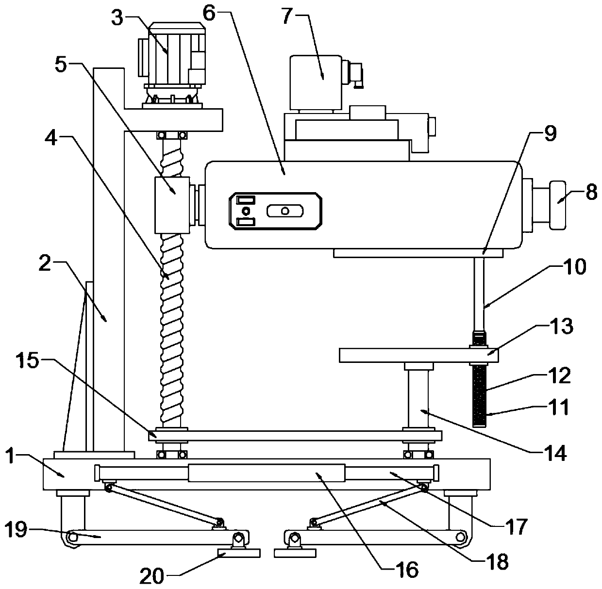
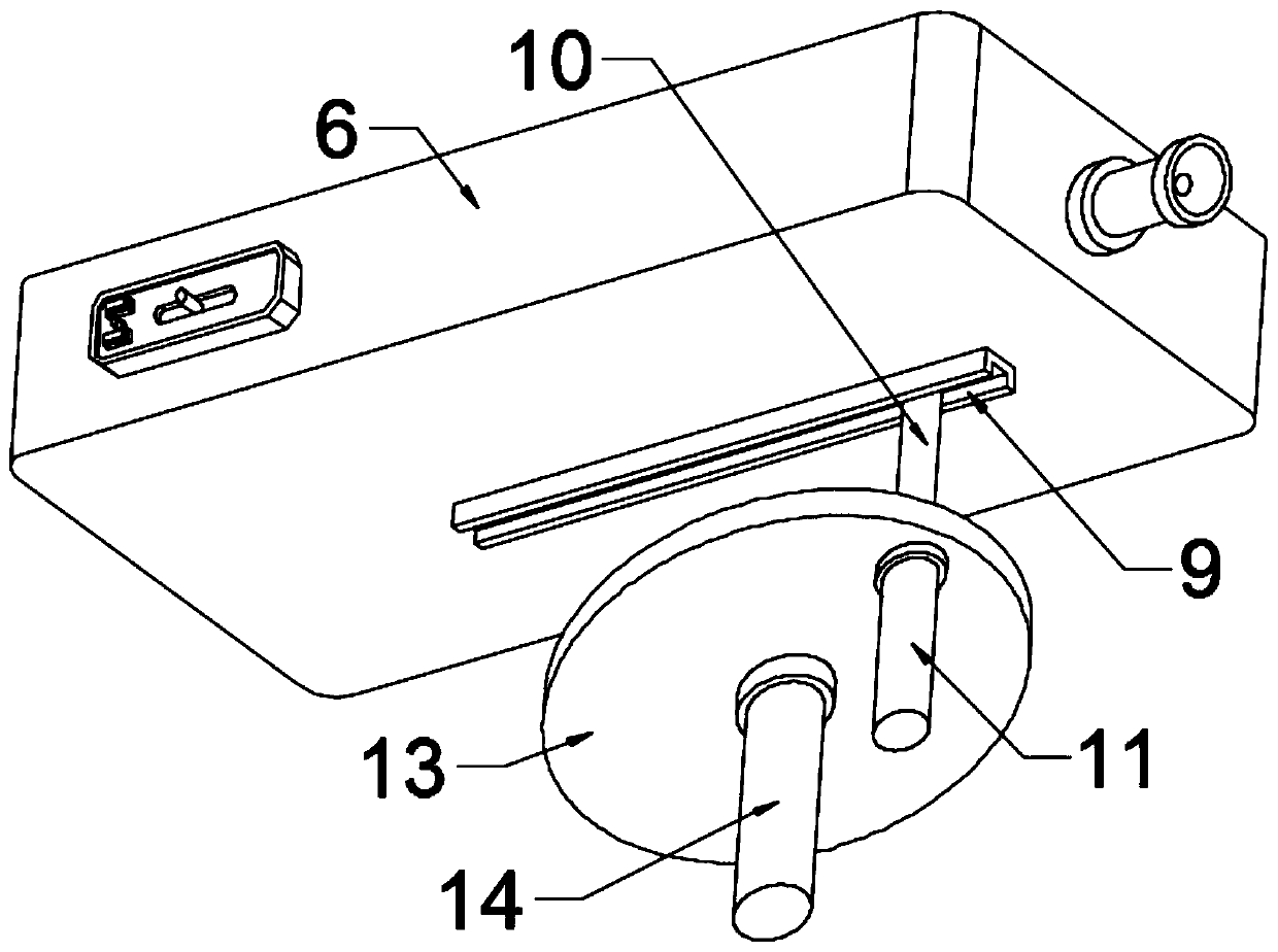
[0022] see Figure 1~3 , in an embodiment of the present invention, an automatic capture projection device for film and television animation playback, including a base plate 1, a back plate 2 fixed to the rear of the base plate 1 through reinforcing ribs, a servo motor 3 installed on the top of the back plate 2, and a servo motor connected to the The height adjustment assembly at the output end of the motor 3, the swing assembly connected to the height adjustment assembly, the projector 6, and the infrared capture device 7 installed above the projector 6;

[0023] Specifically, the height adjustment assembly includes a screw 4 connected to the servo motor 3, a threaded sleeve 5 that is threadedly connected with the screw 4 and fixed at the rear of the projector 6, wherein the lower end of the screw 4 is connected to the bottom plate through a bearing 1, the servo motor 3 is electrically connected to the power supply and the switch through a wire, and the front end of the proje...

Embodiment 2

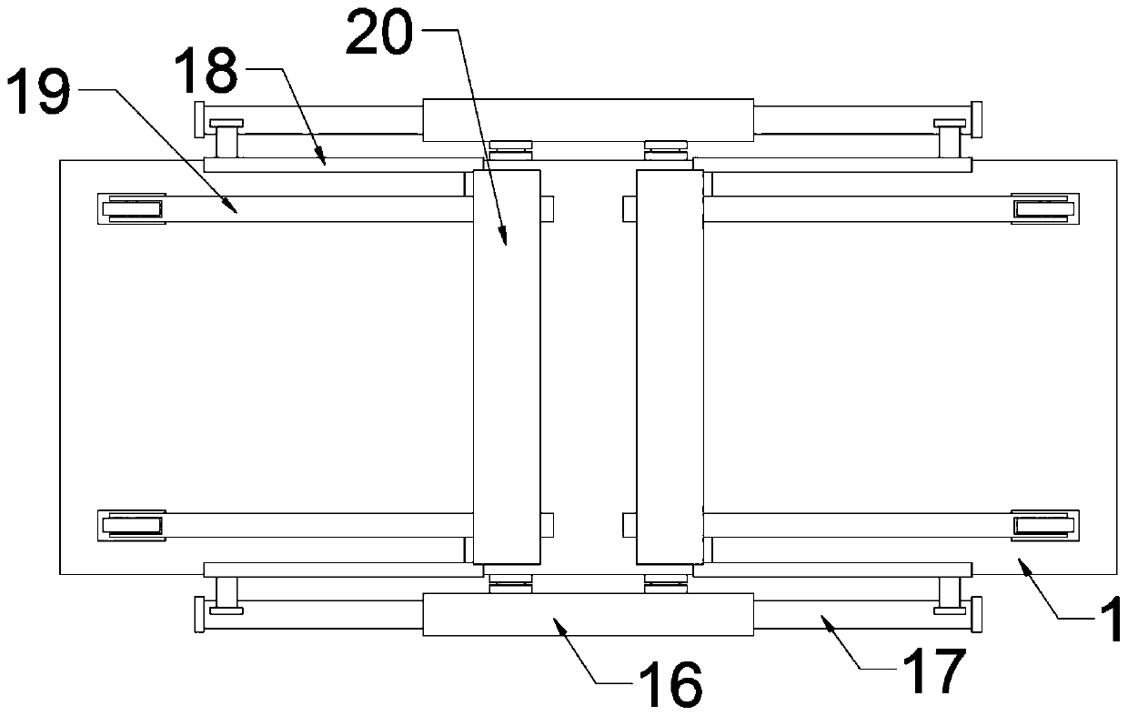
[0028] Obviously, the capture range in the above-mentioned embodiments is still limited. In order to further expand the capture search range, in another embodiment of the present invention, an automatic capture projection device for film and television animation playback also includes a lift-off and landing assembly, and the lift-off and landing assembly includes The double-headed cylinder 16 installed on both sides of the base plate 1, the piston rod 17 slidingly connected to the double-headed cylinder 16 both sides, the connecting rod 18 connecting the piston rod 17 and the lifting arm 19, wherein the end of the lifting arm 19 is hinged on Below the bottom plate 1, the lifting arm 19 rotates to the other side of the joint with the bottom plate 1 to connect the lower end of the connecting rod 18, and the upper end of the connecting rod 18 is rotatably connected to the end of the piston rod 17, and the double-headed cylinder 16 drives the piston rods on both sides. 17 telescopi...


PUM


Abstract

The invention discloses automatic capture projection equipment for television animation playing, particularly, a servo motor drives a screw rod to rotate to drive a threaded sleeve, a projector and aninfrared capture instrument to ascend and descend, the screw rod rotates, and meanwhile a transmission piece drives a driven shaft and a mounting disc to rotate in a following mode so as to achieve transverse capture. The problem that existing playing projection equipment can only play the fixed position, and consequently the direction needs to be manually adjusted is effectively solved. A heightadjustment assembly comprises the screw rod connected with the servo motor, and the threaded sleeve connected with the screw rod in a threaded mode and fixed to the rear part of the projector; and aswinging assembly is arranged on the position, opposite to one side of the screw rod, of a bottom plate, and comprises the driven shaft with the lower end in bearing connection with the bottom plate,the mounting disc fixed to the upper end of the driven shaft, and an elastic assembly fixed to the outer edge of the mounting disc and connected with the lower surface of the projector.

Description

technical field [0001] The invention relates to a playback device, in particular to an automatic capture and projection device for video and animation playback. Background technique [0002] With the development of hardware equipment, the carriers for transmitting animation are increasing rapidly. In addition to traditional TV and movies, mobile devices such as the Internet and mobile phones have the function of playing multimedia files, which provides a broad platform for animation creation. [0003] The animation and multimedia industry has the characteristics of today's knowledge economy and involves various industries such as culture, art, technology, media, publishing, and commerce. In Europe, America, Japan, South Korea and other countries, a complete and mature industrial chain has been formed, and a virtuous cycle structure of input and output has been formed, which has brought considerable economic and social benefits to the animation and multimedia industries. [...

Claims


Application Information

Patent Timeline
Patent Type & Authority Applications(China)
IPC IPC(8): F16M11/04F16M11/08F16M11/18F16M11/38G03B21/54
CPCF16M11/046F16M11/08F16M11/18F16M11/38G03B21/54
Inventor 李静周亮
Owner CHONGQING JIANZHU COLLEGE
Learn More