
Positionable panoramic three-dimensional imaging system and positioning method thereof

A three-dimensional imaging and positioning method technology, applied in stereo systems, image communication, optics, etc., can solve the problems of inability to locate target points, affecting the intensity or direction of laser or structured light, and measurement errors of target positioning points, so as to reduce time errors. , to ensure consistency, and to expand the effect of positioning

Pending Publication Date: 2020-06-09
深圳市人机共识科技有限公司
View PDF1 Cites 2 Cited by
  • Summary
  • Abstract
  • Description
  • Claims
  • Application Information

AI Technical Summary

Problems solved by technology

[0005] However, the above-mentioned technical solution has the following problems: when the target positioning point and the imaging system are on both sides of a transparent object (such as glass), since the laser light or structured light passes through the surface of the transparent object, reflection and refraction will occur, affecting the intensity or intensity of the laser light or structured light. direction, resulting in an error in the measurement of the target positioning point, and it is impossible to locate the target point that is visible in the actual field of view, so it needs to be improved

Method used


Image

  • Positionable panoramic three-dimensional imaging system and positioning method thereof
  • Positionable panoramic three-dimensional imaging system and positioning method thereof
  • Positionable panoramic three-dimensional imaging system and positioning method thereof

Examples


Embodiment Construction

[0042] The technical solutions of the present invention will be clearly and completely described below in conjunction with the accompanying drawings. Apparently, the described embodiments are some of the embodiments of the present invention, but not all of them. Based on the embodiments of the present invention, all other embodiments obtained by persons of ordinary skill in the art without making creative efforts belong to the protection scope of the present invention.

[0043]In the description of the present invention, it should be noted that the terms "center", "upper", "lower", "left", "right", "vertical", "horizontal", "inner", "outer" etc. The indicated orientation or positional relationship is based on the orientation or positional relationship shown in the drawings, and is only for the convenience of describing the present invention and simplifying the description, rather than indicating or implying that the referred device or element must have a specific orientation, o...


PUM


Abstract

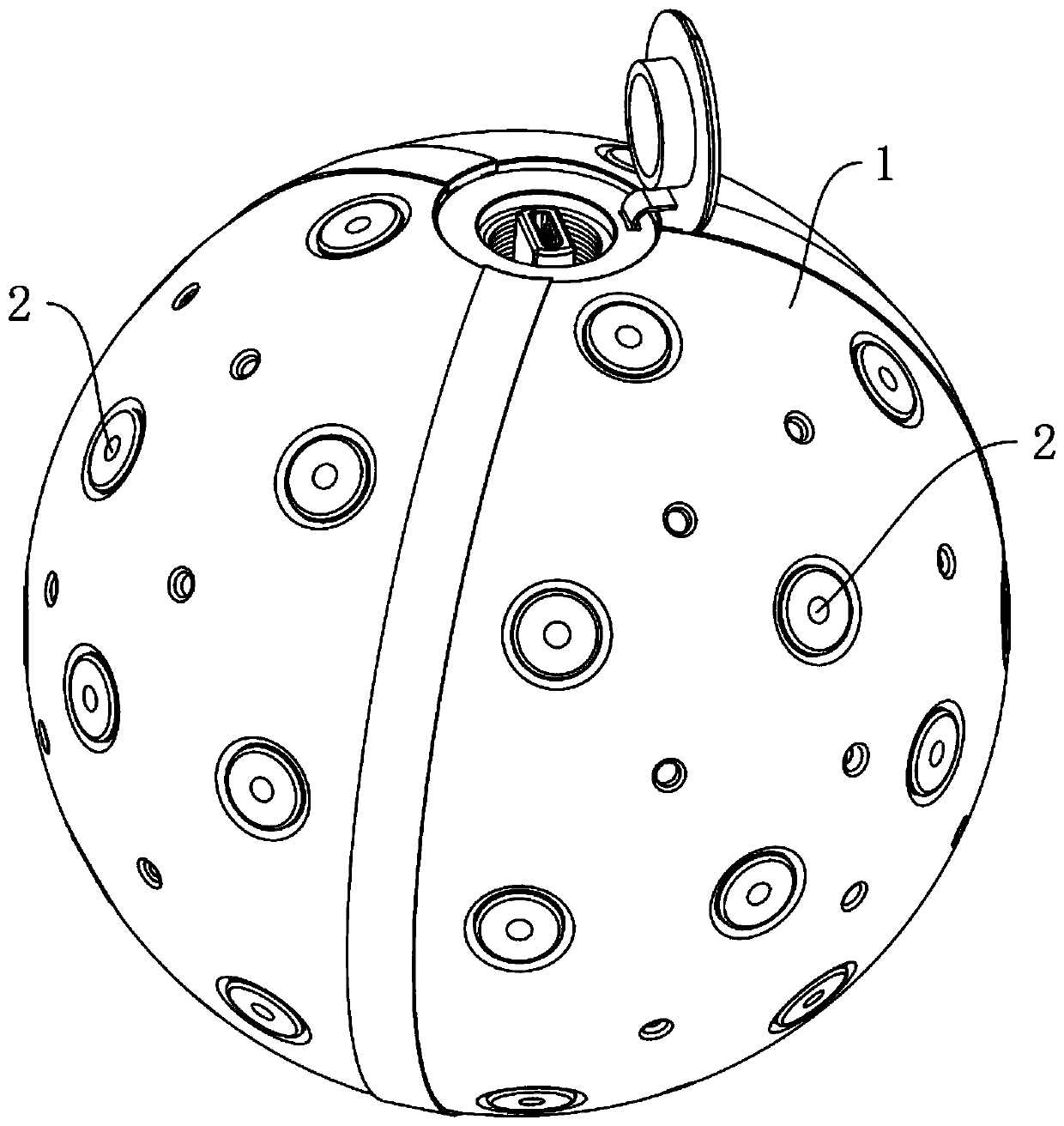
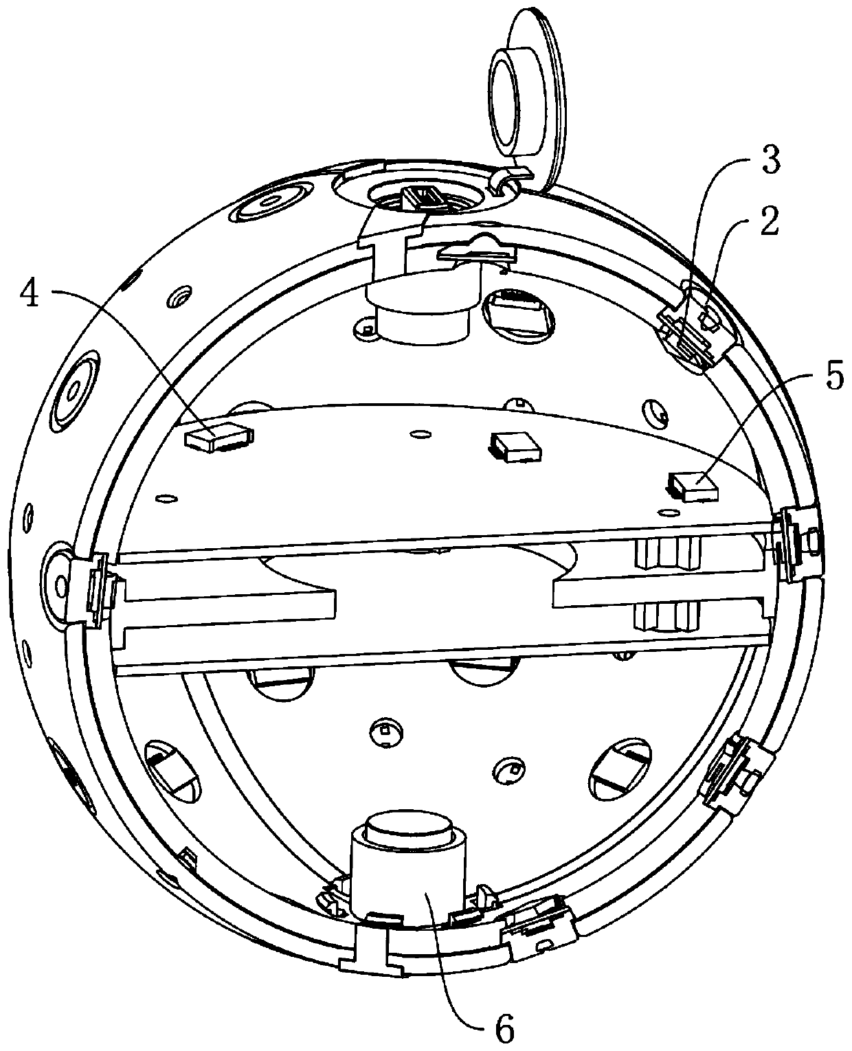
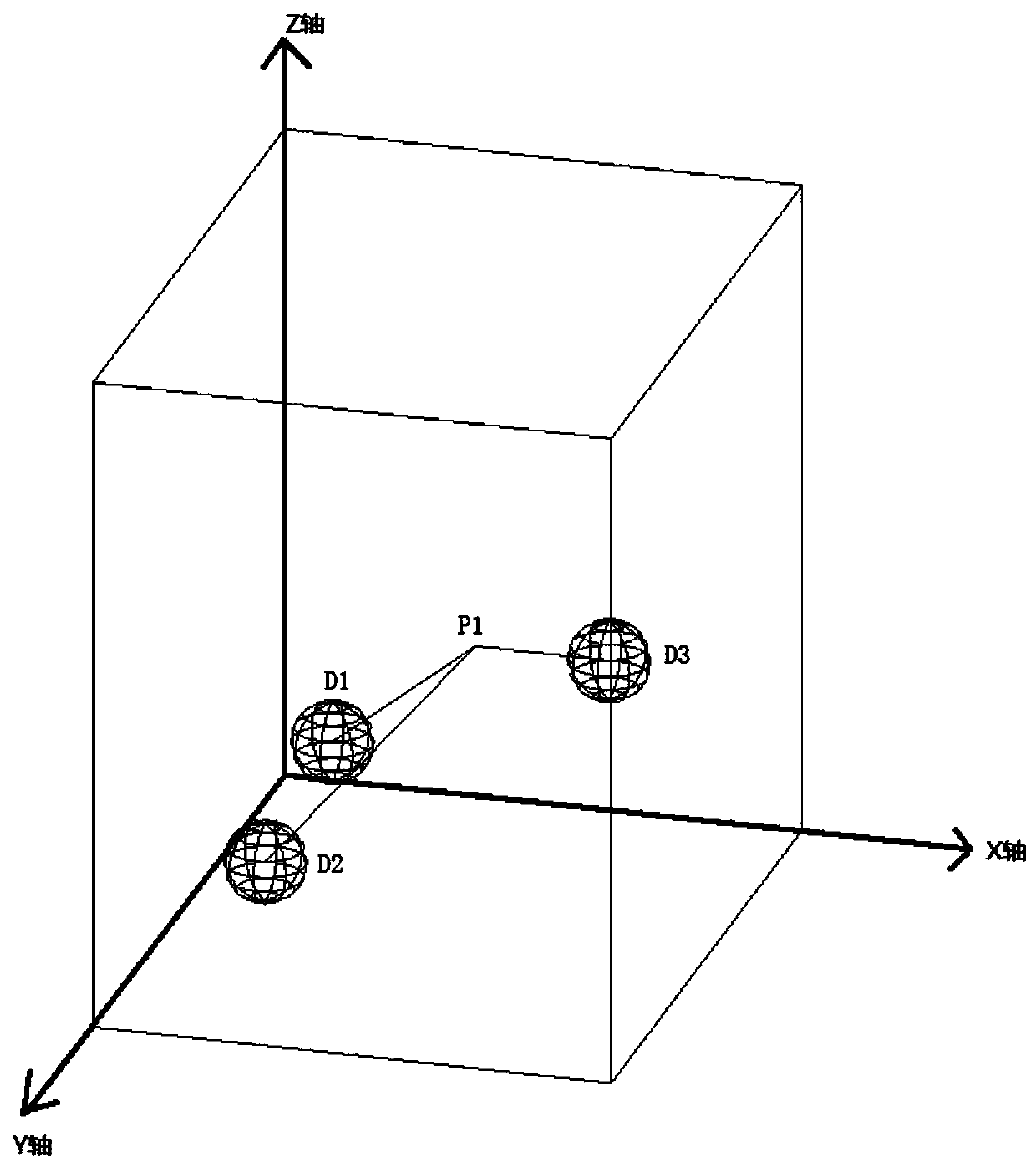
The invention belonging to the image acquisition system field provides a positionable panoramic three-dimensional imaging system and a positioning method thereof. The panoramic three-dimensional imaging system comprises camera shooting control equipment, at least two spherical camera shooting devices, and a data processing unit. Each spherical camera shooting device comprises at least three lens groups and an image sensor for receiving optical signals of the lens groups. The camera shooting control equipment is used for controlling all the spherical camera shooting devices to shoot target points at the same time; the two spherical camera devices form a first panorama and a second panorama respectively, the first panorama and the second panorama have an shooting overlapping area, and a target point is located in the shooting overlapping area. Therefore, problems that when a target positioning point and an imaging system are located on the two sides of a transparent object, laser or structured light can be reflected and refracted after passing through the surface of the transparent object and the intensity or direction of the laser or structured light is affected, and thus errors occur in measurement of the target positioning point, and the target point with the visible actual view cannot be located are solved.

Description

technical field [0001] The invention relates to an image acquisition system, in particular to a positionable panoramic three-dimensional imaging system and a positioning method. Background technique [0002] At present, in the field of forensic science / in case scene investigation / in the process of criminal photography, the main way to record and reproduce the court scene / case scene / crime scene is to use various camera systems (machines) to The shooting and recording of the real scene is a two-dimensional video image recording, and the data, information and traces are all two-dimensional. my country's public security and other law enforcement agencies urgently need to use 3D panoramic image technology in on-site inspection scenes to make up for the shortcomings of traditional criminal photography in 2D images, and improve the efficiency of case analysis, case study and judgment, and joint case investigation. [0003] The invention patent of the existing application publicati...

Claims


Application Information

Patent Timeline
Patent Type & Authority Applications(China)
IPC IPC(8): H04N13/243H04N13/296G03B37/04
CPCH04N13/243H04N13/296G03B37/04H04N2013/0088
Inventor 尹元昌郭培程
Owner 深圳市人机共识科技有限公司
Learn More