
Target area information generation method and target pattern processing method and system

A technology of target area and target pattern, which is applied in the field of target area information generation method, target pattern processing method and system field, can solve problems such as excessive deformation of target pattern and inability for users to identify smoothly.

Active Publication Date: 2019-10-22
CHENGDU XGIMI TECH CO LTD
View PDF8 Cites 0 Cited by
  • Summary
  • Abstract
  • Description
  • Claims
  • Application Information

AI Technical Summary

Problems solved by technology

However, rectification will lead to a certain degree of compression or distortion of the picture content in the original image. If the original image content contains a certain target pattern, when the user needs to complete the follow-up business operations by identifying the target pattern, the target pattern will appear If the deformation is too large, the user cannot recognize it smoothly

Method used


Image

  • Target area information generation method and target pattern processing method and system
  • Target area information generation method and target pattern processing method and system
  • Target area information generation method and target pattern processing method and system

Examples


Embodiment 1

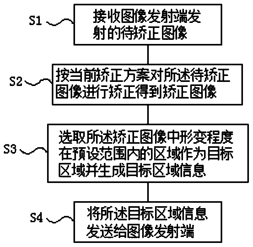
[0053] Such as figure 1 As shown, this embodiment provides a method for generating target area information, which is applied to the image correction terminal, including:

[0054] S1: Receive the image to be corrected transmitted by the image transmitter;

[0055] S2: Correct the image to be corrected according to the current correction scheme to obtain a corrected image;

[0056] S3: Select an area in the corrected image whose deformation degree is within a preset range as a target area and generate target area information.

[0057] In this embodiment, the image to be corrected in step S1 can be a reference image pre-stored by the image transmitter, or an image to be transmitted that the image transmitter is going to transmit for the user to watch. If it is a reference image, it is necessary to make the reference image in the image The pixel range of the transmitting end is the same as the pixel range of the image to be transmitted at the image transmitting end, so as to ens...

Embodiment 2

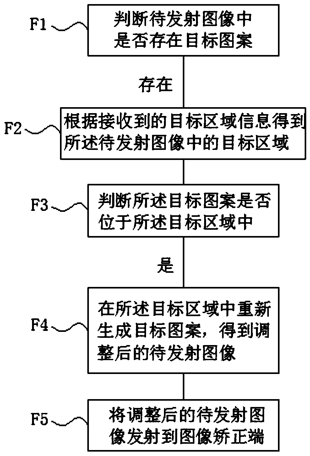
[0077] Such as image 3 As shown, this embodiment provides a target pattern processing method, which is applied to the image transmitting end, including:

[0078] F1: Determine whether there is a target pattern in the image to be transmitted, and if so, proceed to the next step;

[0079] F2: Obtain the target area in the image to be transmitted according to the received target area information;

[0080] F3: judging whether the target pattern is located in the target area, if not, go to the next step;

[0081] F4: Regenerate the target pattern in the target area to obtain the adjusted image to be launched;

[0082] Among them, the method provided by Implementation 1 is used to generate the target area information.

[0083] When this embodiment is specifically implemented, F5 is also included: transmitting the adjusted image to be transmitted to the image correction terminal. After the image correction terminal receives the image (current image to be corrected) transmitted b...

Embodiment 3

[0105] Such as Figure 4 As shown, this embodiment provides an image processing system, including:

[0106] Image correction terminal: used to generate target area information according to the method provided in Embodiment 1, and also used to send the target area information to the image transmitter;

[0107] Image transmitting end: used to adjust the image to be transmitted according to the method provided in Embodiment 2, and also used to transmit the adjusted image to be transmitted to the image correction end.

[0108] The specific method execution processes of the image correction end and the image transmission end in this embodiment have been described in detail in related method embodiments, and will not be described in detail here.


PUM


Abstract

The invention discloses a target area information generation method and a target pattern processing method. The target area information generation method comprises the steps of receiving a to-be-corrected image transmitted by an image transmitting end; correcting the to-be-corrected image according to a current correction scheme to obtain a corrected image; selecting an area of which the deformation degree is within a preset range in the corrected image as a target area and generating target area information. The target pattern processing method comprises the steps of judging whether a targetpattern exists in a to-be-emitted image or not; obtaining a target area in the to-be-emitted image according to the received target area information; judging whether the target pattern is located in the target area or not; and regenerating a target pattern in the target area to obtain an adjusted to-be-emitted image. According to the invention, deformation generated after the target pattern is corrected by the image correction end does not influence identification of the target pattern.

Description

technical field [0001] The invention relates to the field of image processing, in particular to a method for generating target area information, a method and system for processing target patterns. Background technique [0002] The original image emitted by the image signal source often needs to be corrected before being displayed on the image display, so that the image displayed on the image display has a better outline. For example, in many scenes, the image projected by the projection device needs to It is first corrected by the keystone correction module and then put on the projection surface. The purpose of this is to make the projected picture on the projection surface appear rectangular, so that users can have a better viewing experience. However, rectification will lead to a certain degree of compression or distortion of the picture content in the original image. If the original image content contains a certain target pattern, when the user needs to complete the follo...

Claims


Application Information

Patent Timeline
Patent Type & Authority Applications(China)
IPC IPC(8): G06T5/00
CPCG06T2207/20021G06T5/80
Inventor 钟波肖适王鑫秦明亮龙冬
Owner CHENGDU XGIMI TECH CO LTD
Learn More