Projection device

A projection device and projection lens technology, applied in the field of optics, can solve problems such as poor projection imaging effect, inability to improve pixels, and inability to meet the requirements of high-definition look and feel of projected images, and achieve the effect of improving resolution and expanding pixel resolution

Inactive Publication Date: 2019-10-22
GOERTEK OPTICAL TECH CO LTD
View PDF5 Cites 5 Cited by
  • Summary
  • Abstract
  • Description
  • Claims
  • Application Information

AI Technical Summary

Problems solved by technology

The pixels of DLP projection display equipment cannot be improved, resulting in poor projection imaging effect, which cannot meet people's requirements for high-definition perception of projected images.

Method used

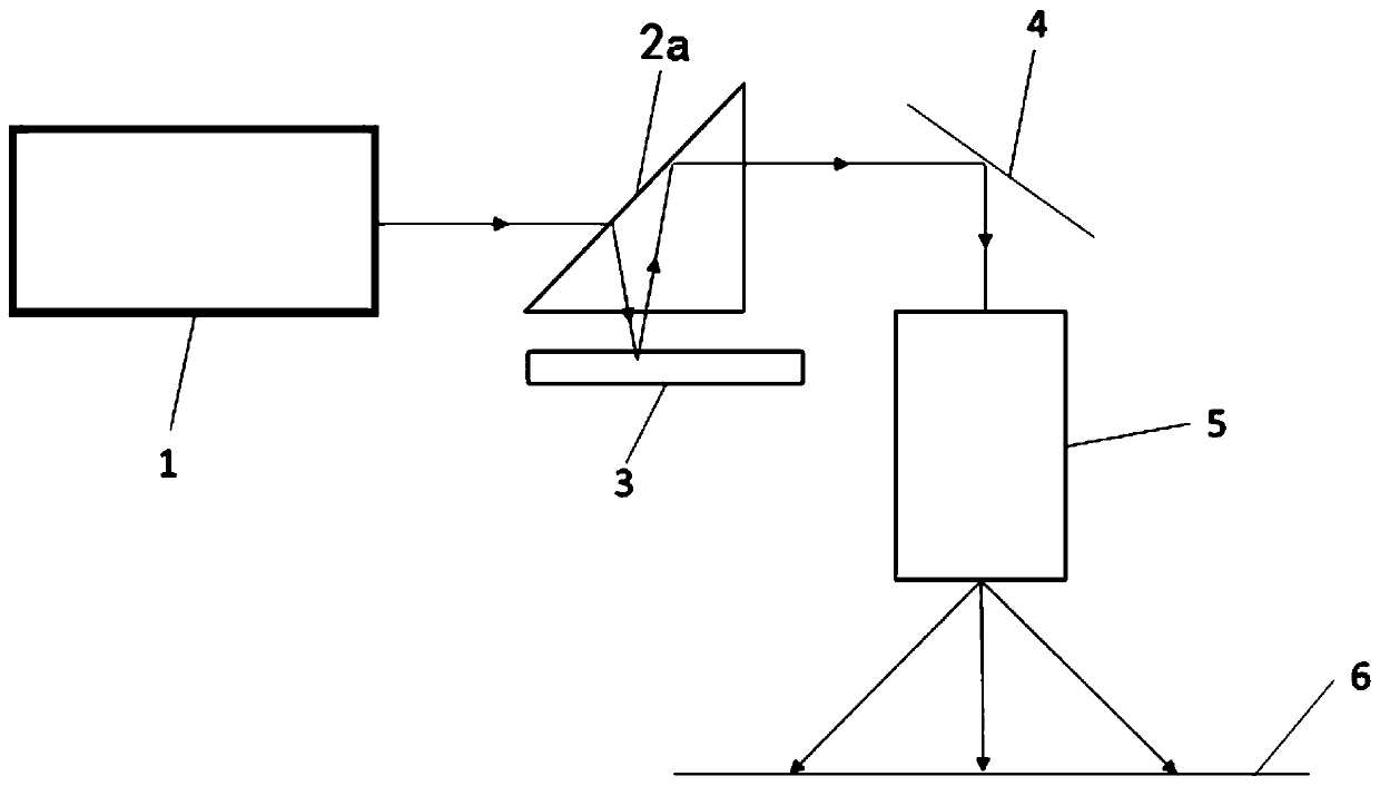
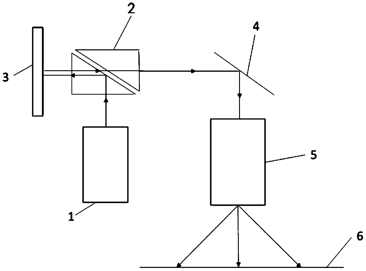
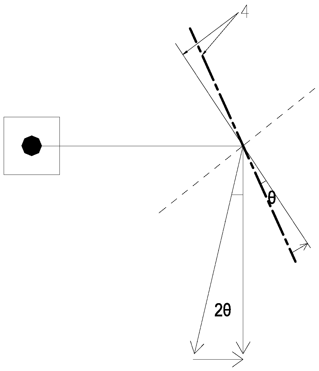

Image

  • Projection device
  • Projection device
  • Projection device

Examples


Embodiment Construction

[0030] Various exemplary embodiments of the present invention will now be described in detail with reference to the accompanying drawings. It should be noted that the relative arrangements of components and steps, numerical expressions and numerical values ​​set forth in these embodiments do not limit the scope of the present invention unless specifically stated otherwise.

[0031] The following description of at least one exemplary embodiment is merely illustrative in nature and in no way taken as limiting the invention, its application or uses.

[0032] Techniques, methods and devices known to those of ordinary skill in the relevant art may not be discussed in detail, but where appropriate, such techniques, methods and devices should be considered part of the description.

[0033] In all examples shown and discussed herein, any specific values ​​should be construed as exemplary only, and not as limitations. Therefore, other instances of the exemplary embodiment may have dif...


PUM


Abstract

The invention discloses a projection device. The projection device comprises a lighting source, a reflecting prism, a DMD module and a rotatable reflecting mirror, wherein the lighting source, the reflecting prism and the rotatable reflecting mirror are arranged in sequence; light emitted by the lighting source is coupled with the DMD module through the reflecting prism; the light enters the rotatable reflecting mirror and is reflected by the rotatable reflecting mirror; and the rotatable reflecting mirror is configured to rotate around a first shaft in a reciprocating manner and rotate arounda second shaft in a reciprocating manner after a set time length is delayed under the condition that the DMD module is opened, so that a single pixel is expanded in the direction perpendicular to thefirst shaft and the direction perpendicular to the second shaft.

Description

technical field [0001] The present invention relates to the field of optical technology, and more specifically, to a projection device. Background technique [0002] A DLP projection display device usually includes an illumination source, a TIR prism, a DMD module and a projection lens. An illumination source is used to emit light. The TIR prism receives the light beam from the illumination source, refracts it and sends it out to the DMD module. The DMD module is used to reflect the beam from the TIR prism back to the TIR prism. After the TIR prism converts the light path of the light beam, the light beam enters the projection lens. The light beam is enlarged by the projection lens and then projected into an image. [0003] However, the pixels of the existing DLP projection display device depend on the size of the micro-mirrors of the DMD module. In general, the size of the micromirrors is fixed. The pixels of DLP projection display equipment cannot be improved, result...

Claims


Application Information

Patent Timeline
IPC IPC(8): H04N9/31G03B21/28
CPCG03B21/28H04N9/3141
Inventor 崔中秋鲁公涛
Owner GOERTEK OPTICAL TECH CO LTD
Why Eureka
Try Eureka