Floor supporting structure and manufacturing method thereof

A supporting structure and manufacturing method technology, applied in the direction of floors, building structures, building components, etc., can solve the problems of long production cycle and high cost, and achieve the effect of short production cycle, low cost and cost reduction

Pending Publication Date: 2019-10-25
盈创新材料(苏州)有限公司
View PDF0 Cites 3 Cited by
  • Summary
  • Abstract
  • Description
  • Claims
  • Application Information

AI Technical Summary

Problems solved by technology

[0002] The traditional method of steel truss floor slab is to build the building formwork first and then pour the concrete. After the building structure is completed, the GRG (Glass Fiber Reinforced Gypsum, pre-cast glass fiber reinforced gypsum board) ceiling is installed, and the structure and decoration are separated. , so that on-site operations are required, the production cycle is long and the cost is high

Method used


Image

  • Floor supporting structure and manufacturing method thereof
  • Floor supporting structure and manufacturing method thereof
  • Floor supporting structure and manufacturing method thereof

Examples


Embodiment 1

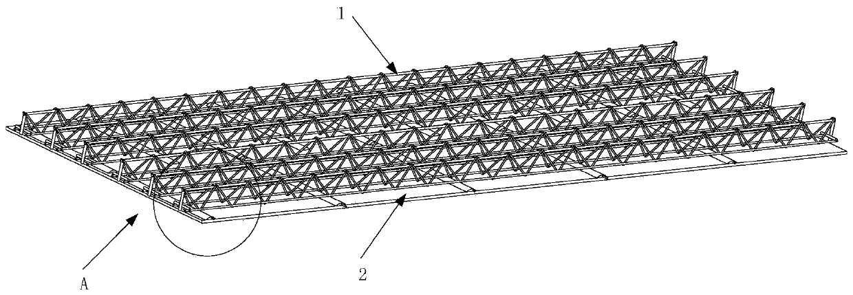
[0090] Such as Figure 9 As shown, a method for manufacturing a floor support structure according to the present invention includes:

[0091] Step S101, laying part of the formwork body, and one side of part of the formwork body is a decorative surface;

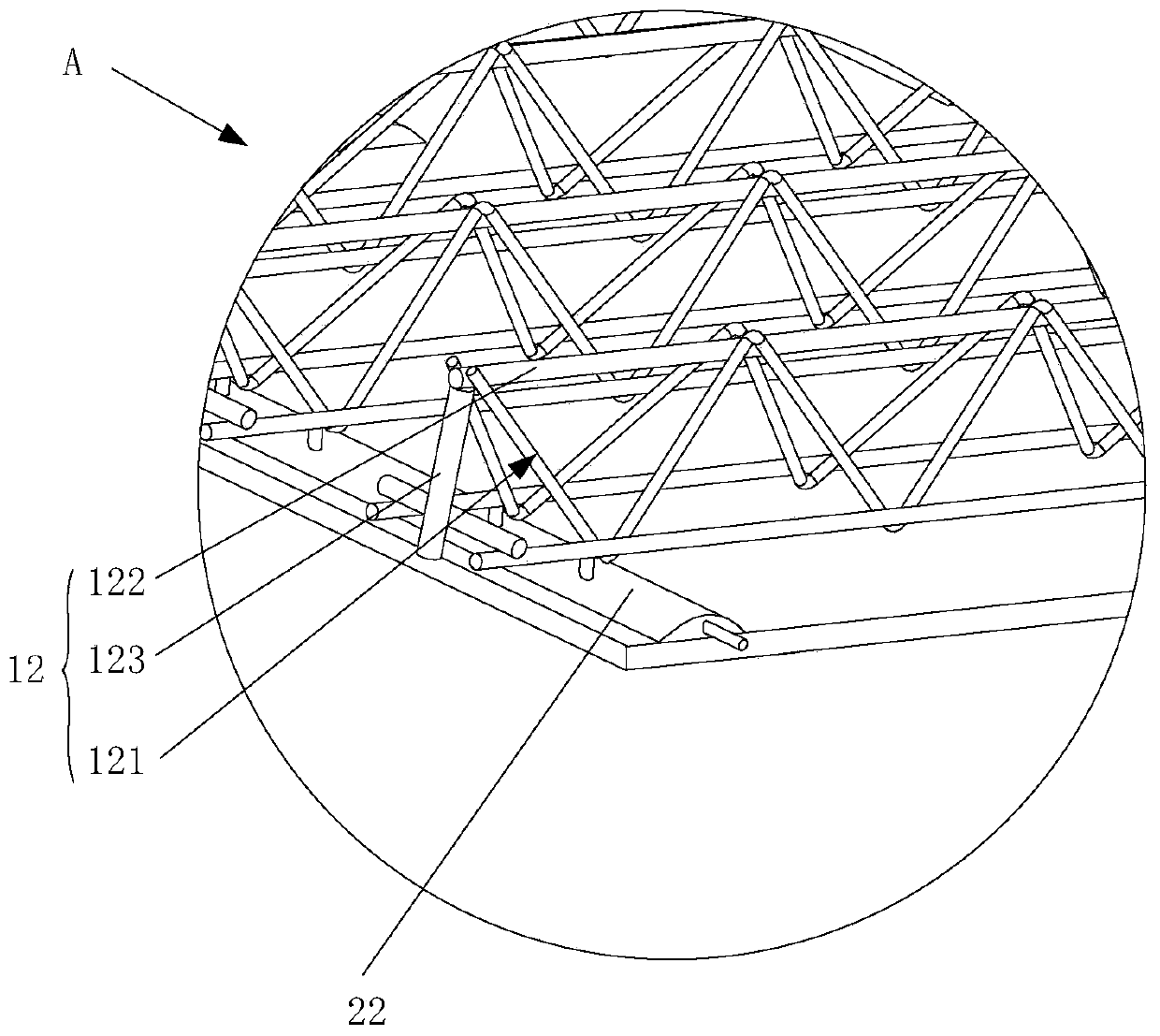
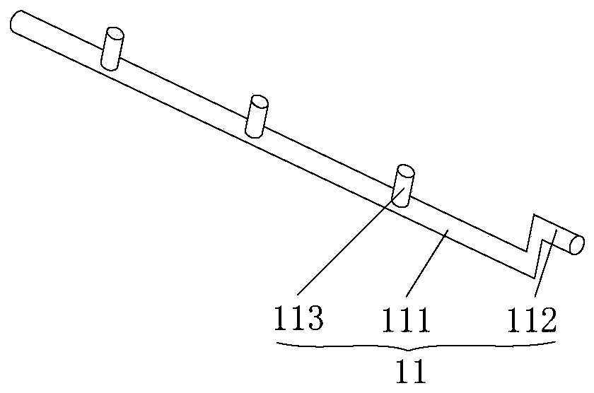
[0092] Step S102, placing the truss assembly on the side of the partial formwork body away from the decorative surface;

[0093] Step S103, laying the remaining formwork body, so as to pre-embed at least part of the truss components in the formwork body, and form a reserved space for pouring concrete between the truss components and the formwork body.

[0094] The specific operation process is as follows:

[0095] First proceed to step S101, laying part of the formwork body, and one side of the part of the formwork body is the decorative surface; then proceed to step S102, place the truss assembly on the side of the partial formwork body away from the decorative surface, to facilitate the next steps Pre-embed the truss com...

Embodiment 2

[0097] Such as Figure 10 As shown, a method for manufacturing a floor support structure according to the present invention includes:

[0098] First subunit laying step S201, laying felt soaked with gypsum slurry, spraying glass fibers with gypsum slurry to the felt, compacting the glass fibers with gypsum slurry with a compactor, laying mesh cloth on the glass fibers, Use compacting parts to compress the mesh cloth;

[0099] Step S202, repeating the first subunit laying step at least once.

[0100] Step S203, placing the truss assembly on the side of the partial formwork body away from the decorative surface;

[0101] The second subunit laying step S204, laying the felt soaked with gypsum slurry and compacting the felt soaked with gypsum slurry using a compactor, spraying glass fibers with gypsum slurry to the felt and compacting the felt with gypsum slurry using a compactor The glass fiber is laid on the glass fiber, and the mesh cloth is compacted with a compactor, so th...


PUM


Abstract

The invention provides a floor supporting structure and a manufacturing method thereof, and relates to the technical field of building. The floor supporting structure provided by the invention comprises a truss component and a module shell body; the truss component at least partly pre-buried in the module shell body; a preserved space used for pouring concrete is provided between the truss component and the module shell body; and the side, which is back to the truss component, of the module shell body is a decorative surface. By adopting the floor supporting structure, decoration and the supporting structure can be performed synchronously; both a supporting function and a decoration function are realized; concrete pouring does not need to be performed before on-site decoration work; the production cycle is short; and cost is low.

Description

technical field [0001] The invention relates to the technical field of buildings, in particular to a floor support structure and a manufacturing method thereof. Background technique [0002] The traditional method of steel truss floor slab is to build the building formwork first and then pour the concrete. After the building structure is completed, the GRG (Glass Fiber Reinforced Gypsum, pre-cast glass fiber reinforced gypsum board) ceiling is installed, and the structure and decoration are separated. , so that on-site operations are required, the production cycle is long and the cost is high. Contents of the invention [0003] The purpose of the present invention is to provide a floor support structure and its manufacturing method, which can realize the synchronous operation of decoration and support structure, without pouring concrete before performing on-site decoration operation, with short production cycle and low cost. [0004] To achieve the above object, the prese...

Claims


Application Information

Patent Timeline
Patent Type & Authority Applications(China)
IPC IPC(8): E04B5/32E04B5/36
CPCE04B5/32E04B5/36
Inventor 马义和
Owner 盈创新材料(苏州)有限公司
Why Eureka
Try Eureka