A pcb board welding device based on double board clamping technology

A PCB board and soldering device technology, applied in the PCB field, can solve the problems of long soldering time, difficult soldering, difficulty in meeting modern production needs, etc., and achieve the effects of improving processing efficiency, facilitating reverse processing, and improving convenience

Inactive Publication Date: 2021-03-30
SHANGQIU INST OF TECH
View PDF9 Cites 0 Cited by
  • Summary
  • Abstract
  • Description
  • Claims
  • Application Information

AI Technical Summary

Problems solved by technology

[0004] At present, in the PCB board welding jigs on the market, when the pins of the electronic components are inserted into the PCB board, the PCB board needs to be flipped, and the soldering is performed on the reverse side of the PCB board. However, the existing jigs cannot provide flipping, which makes welding difficult. , the welding time is too long, it is difficult to meet the needs of modern production

Method used


Image

  • A pcb board welding device based on double board clamping technology
  • A pcb board welding device based on double board clamping technology
  • A pcb board welding device based on double board clamping technology

Examples


Embodiment 1

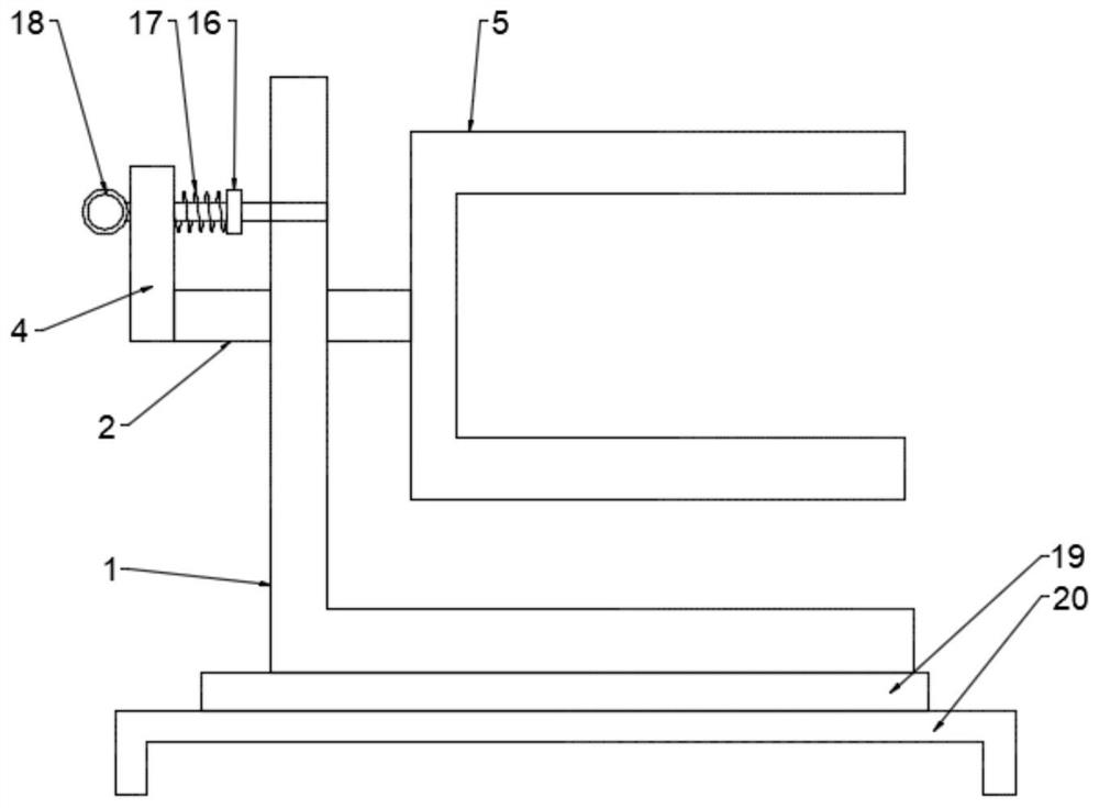
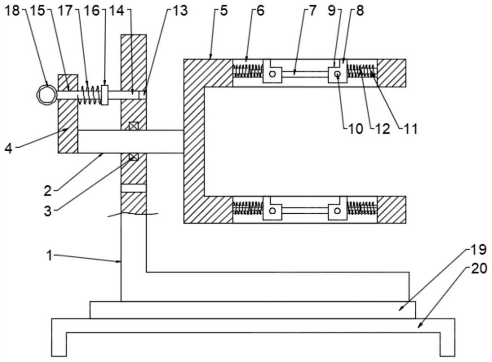
[0026] see Figure 1~3 , a PCB board welding device based on double-board clamping technology, including a bracket 1, the bracket 1 is an L-shaped structure, the side wall of the bracket 1 is embedded with a rotating shaft 2, and the rotating shaft 2 is rotatably connected to the bracket through a bearing 3 1, the left end of the rotating shaft 2 is fixedly connected to the toggle lever 4, the other end of the toggle lever 4 is provided with a positioning mechanism, and the right end of the rotating shaft 2 is fixedly connected to the support frame 5, and the support frame 5 is U-shaped structure, the side wall of the support frame 5 is provided with a clamping cavity 6, and a clamping mechanism is provided in the clamping cavity 6, and the PCB board is installed in the clamping cavity 6 through the clamping mechanism, and two PCB boards are clamped at a time, It can realize the synchronous operation of two PCB boards and improve the processing efficiency; loosen the positioni...

Embodiment 2

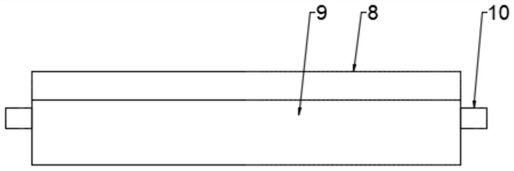
[0028] This embodiment is a further elaboration on the basis of Embodiment 1. The clamping mechanism includes a chute 7, a push clamp 8 and a telescopic rod 11. The front and rear walls of the cavity 6 are symmetrically provided with a chute 7, The left and right sides of the inner cavity of the card cavity 6 are symmetrically provided with push clips 8 matched with the chute 7, and there is a sliding connection between the card cavity 6 and the push clip 8, and the front and rear ends of the push clip 8 are symmetrically arranged with the chute. 7 is matched with the sliding pin 10, which is a sliding connection between the sliding pin 10 and the chute 7, and the push clip 8 can slide left and right along the chute 7 through the mutual cooperation of the sliding pin 10 and the chute 7.

[0029] The top adjacent side of the push clip 8 is provided with a clip groove 9, and one end of the push clip 8 opposite to the clip groove 9 is fixedly connected to the telescopic rod 11, an...

Embodiment 3

[0031] This embodiment is a further elaboration on the basis of Embodiment 1. The positioning mechanism includes a positioning rod 14 and two positioning holes 13, and the two positioning holes 13 are symmetrically arranged on the upper and lower sides of the side wall of the bracket 1. The rotating shaft 2 is arranged in the center between the two positioning holes 13, and the rotating angle of the rotating shaft 2 is positioned by using the positioning holes 13, which reduces the complexity of operation and improves the convenience of processing.

[0032] The overhanging end of the toggle rod 4 is provided with a jack 15, the jack 15 is provided with a positioning rod 14 matched with the positioning hole 13, and the positioning rod 14 is slidingly connected to the jack 15, The left side end of positioning rod 14 is fixedly connected with the finger ring 18 that cooperates with jack 15, and the outer circular surface right side of positioning rod 14 is provided with the baffle...


PUM


Abstract

The invention provides a PCB welding device based on a dual-board clamping technology, and particularly belongs to the technical field of PCBs. The PCB welding device comprises a bracket, and a rotating shaft is arranged on the side wall of the bracket in an embedded mode; the rotating shaft is rotatably connected to the bracket through a bearing, the left side end of the rotating shaft is fixedlyconnected with a shifting rod, and the other end of the shifting rod is provided with a positioning mechanism; the right side end of the rotating shaft is fixedly connected with a supporting frame ofa U-shaped structure, a clamping cavity is formed in the side wall of the supporting frame, and a clamping mechanism is arranged in the clamping cavity; the clamping mechanism comprises sliding grooves, pushing clamps and telescopic rods; and the positioning mechanism comprises a positioning rod and two positioning holes. Through the two pushing clamps in the same clamping cavity, the PCBs are placed between the two pushing clamps and thus are clamped in the clamping cavity, every two PCBs are clamped at a time and thus can be synchronously operated, and the machining efficiency is improved;and the rotating shaft is matched to drive the supporting frame to be overturned and rotate by 180 degrees, the upper end face and the lower end face of the supporting frame are turned, thus the reverse faces of the PCBs are conveniently machined, and machining convenience is improved.

Description

technical field [0001] The invention relates to the technical field of PCB, in particular to a PCB board welding device based on double-board clamping technology. Background technique [0002] Printed circuit board {PCB circuit board}, also known as printed circuit board, is the provider of electrical connections for electronic components. Its development has a history of more than 100 years; its design is mainly layout design; the main advantage of using circuit boards is that it greatly reduces wiring and assembly errors, and improves automation and production labor rates. [0003] Printed circuit boards can be divided into single-sided boards, double-sided boards, four-layer boards, six-layer boards and other multi-layer boards according to the number of board layers. [0004] At present, in the PCB board welding jigs on the market, when the pins of the electronic components are inserted into the PCB board, the PCB board needs to be flipped, and the soldering is performe...

Claims


Application Information

Patent Timeline
Patent Type & Authority Patents(China)
IPC IPC(8): B23K37/04B23K101/42
Inventor 王晓惠蒋琳姚久鹏
Owner SHANGQIU INST OF TECH
Why Eureka
Try Eureka