Watertight locking device and installation method thereof
A locking and locking technology, applied in the direction of building fasteners, buildings, building structures, etc., can solve the problems of increasing the weight of the entire door equipment, increasing the complexity of installation, and increasing the energy consumption of ship operation.
- Summary
- Abstract
- Description
- Claims
- Application Information
AI Technical Summary
Problems solved by technology
Method used
Image

Examples
Embodiment 1
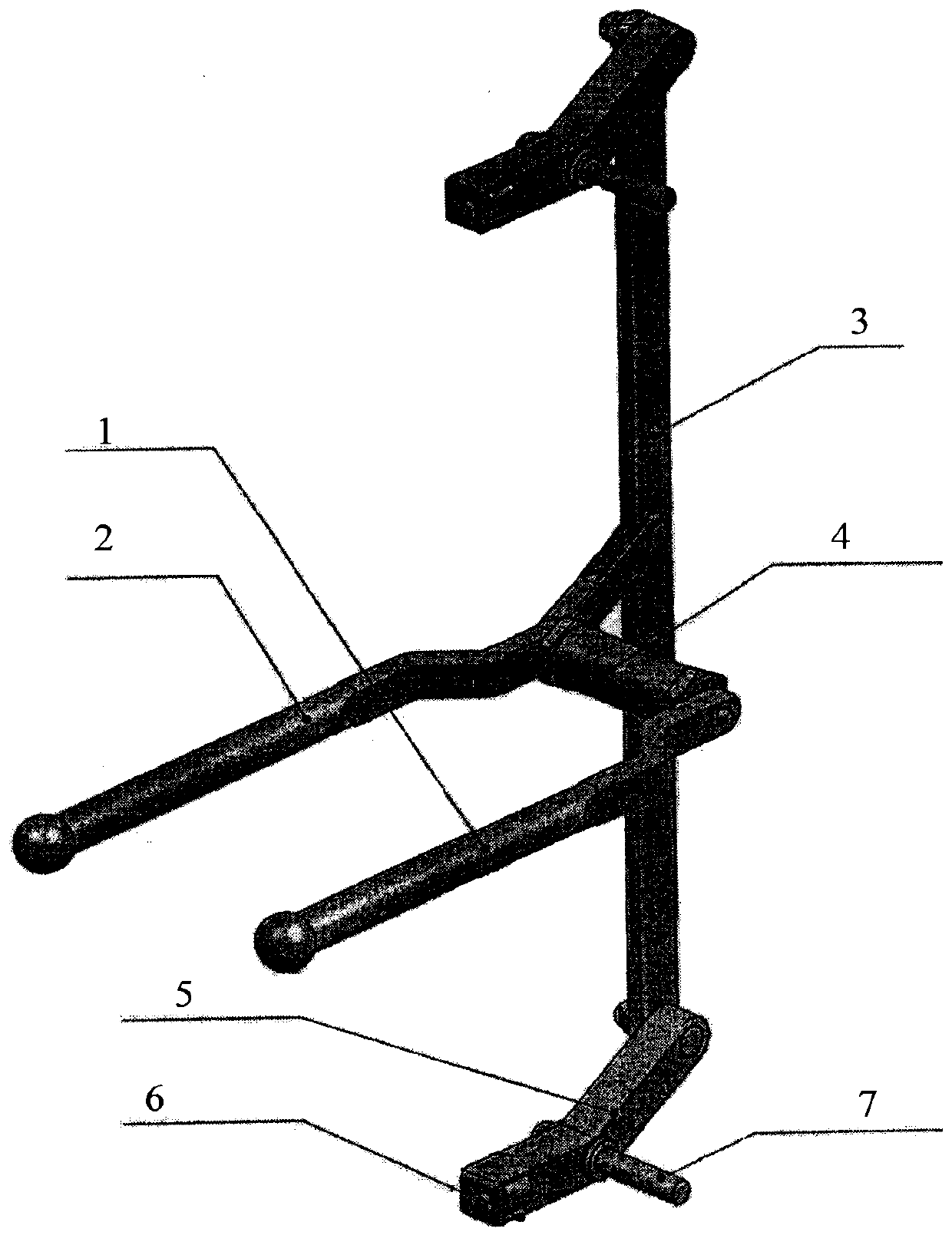
[0037] see figure 1 , a watertight locking device, comprising a connecting rod 3, a door-through sealing kit 4, a rear handle 1, a front handle 2, a locking rotating lever 5 and a door pressing block rotating shaft 7;
[0038] The upper end and the lower end of the connecting rod 3 are each connected to a locking rotary lever 5 by bolts, and the locking rotary lever is composed of two sections of levers forming an obtuse angle each other, and the door pressure is set at the intersection of the two sections of levers Tight block shaft 7,
[0039] The back handle includes a free end of the back handle when opening and closing the door and a fixed end of the back handle located at the other end of the back handle, and the fixed end of the back handle is connected to the door-through sealing kit;
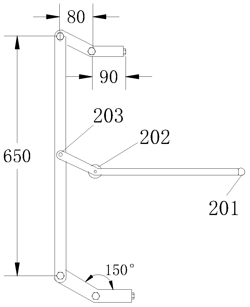
[0040] see figure 2 , the front handle includes a front handle free end 201, a fulcrum 202 and a fixed end 203 of the front handle, and the fulcrum 202 fixes the front handle with th...
Embodiment 2
[0049] The installation method of the watertight locking device described in Embodiment 1 includes:
[0050] passing the door-through sealing kit through the door frame and welding and fixing it with the door frame;
[0051]The rotating shaft of the pressing block on the door is inserted into the door frame from the front of the door and welded firmly (the front of the door refers to the side where the front handle is located);
[0052] The door panel and the door frame are connected by hinges.
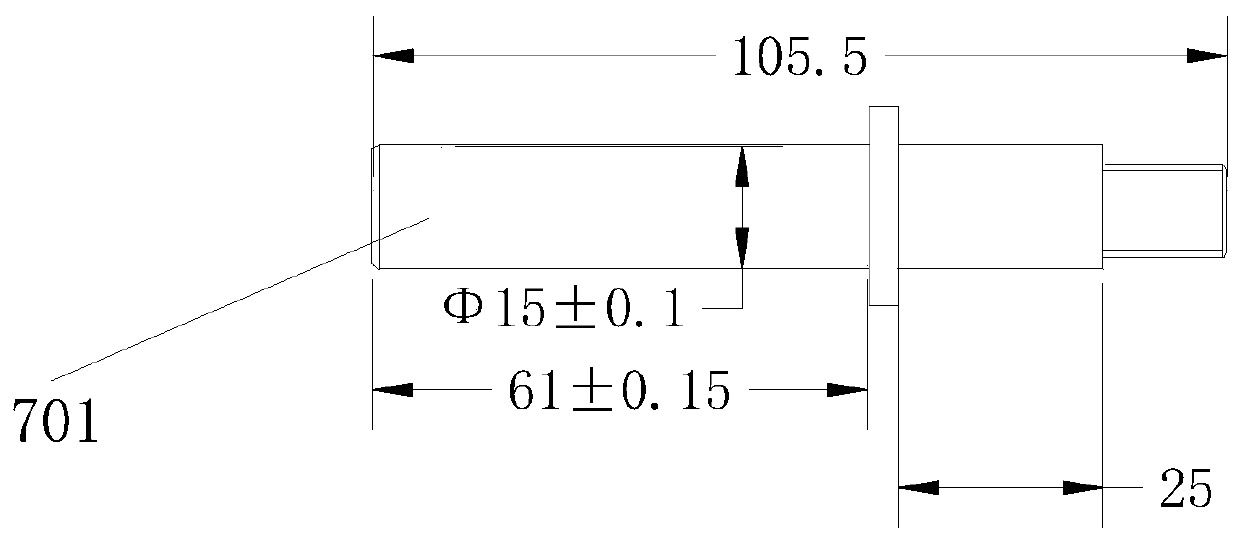
[0053] In this embodiment, the length of the rotating shaft of the front pressing block inserted into the inner part 701 of the door frame is 61±0.15 mm, and the outer diameter of the part inserted into the inner part of the door frame is 15±0.1 mm. The length of the part of the door face pressing block rotating shaft 7 passing through the locking rotary lever is 25mm, and the end of the locking rotary lever passing through is fastened with a nut (M12).
[0054] The watertight locki...
Embodiment 3
[0058] A watertight locking device, comprising a connecting rod 3, a door-through sealing kit 4, a rear handle 1, a front handle 2, a locking rotating lever 5 and a door pressing block rotating shaft 7;
[0059] The upper end and the lower end of the connecting rod are each connected to a locking rotary lever 5, and the locking rotary lever is composed of two sections of levers forming an obtuse angle with each other. 7,
[0060] The back handle includes a free end of the back handle when opening and closing the door and a fixed end of the back handle located at the other end of the back handle, and the fixed end of the back handle is connected to the door-through sealing kit;
[0061] see figure 2 , the front handle includes a front handle free end 201, a fulcrum 202 and a front handle fixed end 203, and the fulcrum fixes the front handle with the door-through sealing kit; the front handle free end and the front handle The fixed end is located on both sides of the fulcrum;...
PUM
 Abstract
Description
Claims
Application Information
 - R&D
- Intellectual Property
- Life Sciences
- Materials
- Tech Scout
- Unparalleled Data Quality
- Higher Quality Content
- 60% Fewer Hallucinations
Browse by: Latest US Patents, China's latest patents, Technical Efficacy Thesaurus, Application Domain, Technology Topic, Popular Technical Reports.
© 2025 PatSnap. All rights reserved.Legal|Privacy policy|Modern Slavery Act Transparency Statement|Sitemap|About US| Contact US: help@patsnap.com