A variable stiffness hourglass spring and its method
- Summary
- Abstract
- Description
- Claims
- Application Information
AI Technical Summary
Problems solved by technology
Method used
Image
Examples
Embodiment 1
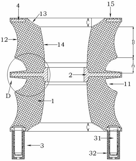
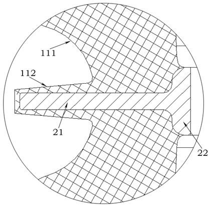
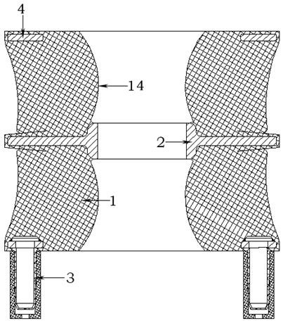
[0026] Such as figure 1 As shown, the hourglass spring includes a rubber body 1, a support rod 2, a foot 3 and an upper end plate 4. There is a cavity vertically penetrating the rubber body 1 on the rubber body 1, and the support rod 2 is embedded in the rubber body 1 in a lateral distribution manner. of the middle. The outer sides of the rubber bodies 1 on both sides of the support rod 2 are provided with outer concave holes 11 , and the rubber bodies 1 on both sides of the outer concave holes 11 are provided with outer concave arc surfaces 12 . The inner side of the rubber body 1 is provided with an inner concave arc surface 13 and an inner convex arc surface 14, and the upper end surface 15 is embedded in the top of the rubber body 1, and the lower end of the rubber body 1 is provided with a leg 3.
[0027] The top and bottom of the rubber body 1 of the hourglass spring are also provided with mounting bases, which are not shown in the figure. When the rubber body 1 of the ...
PUM
 Abstract
Description
Claims
Application Information
 - R&D
- Intellectual Property
- Life Sciences
- Materials
- Tech Scout
- Unparalleled Data Quality
- Higher Quality Content
- 60% Fewer Hallucinations
Browse by: Latest US Patents, China's latest patents, Technical Efficacy Thesaurus, Application Domain, Technology Topic, Popular Technical Reports.
© 2025 PatSnap. All rights reserved.Legal|Privacy policy|Modern Slavery Act Transparency Statement|Sitemap|About US| Contact US: help@patsnap.com


