A Parallel Compound Double Output Shaft Rotating Ultrasonic Motor

An ultrasonic motor, dual output shaft technology, applied in the direction of generator/motor, piezoelectric effect/electrostrictive or magnetostrictive motor, electrical components, etc., can solve the problem of small radial size, short force arm, output torque Small and other problems, to achieve the effect of large torque output, stable output performance, and improved parallel efficiency

Active Publication Date: 2021-09-17
JIANGSU UNIV
View PDF4 Cites 0 Cited by
  • Summary
  • Abstract
  • Description
  • Claims
  • Application Information

AI Technical Summary

Problems solved by technology

The patent [CN201210433818.3] proposes a rotating ultrasonic motor driven by multiple parallel V vibrators, but the disadvantage is that the V vibrator contacts act on the mover (that is, the output shaft), and the radial dimension of the shaft It must be very small, which causes the problem of short arm and small output torque

Method used


Image

  • A Parallel Compound Double Output Shaft Rotating Ultrasonic Motor
  • A Parallel Compound Double Output Shaft Rotating Ultrasonic Motor
  • A Parallel Compound Double Output Shaft Rotating Ultrasonic Motor

Examples


Embodiment 1

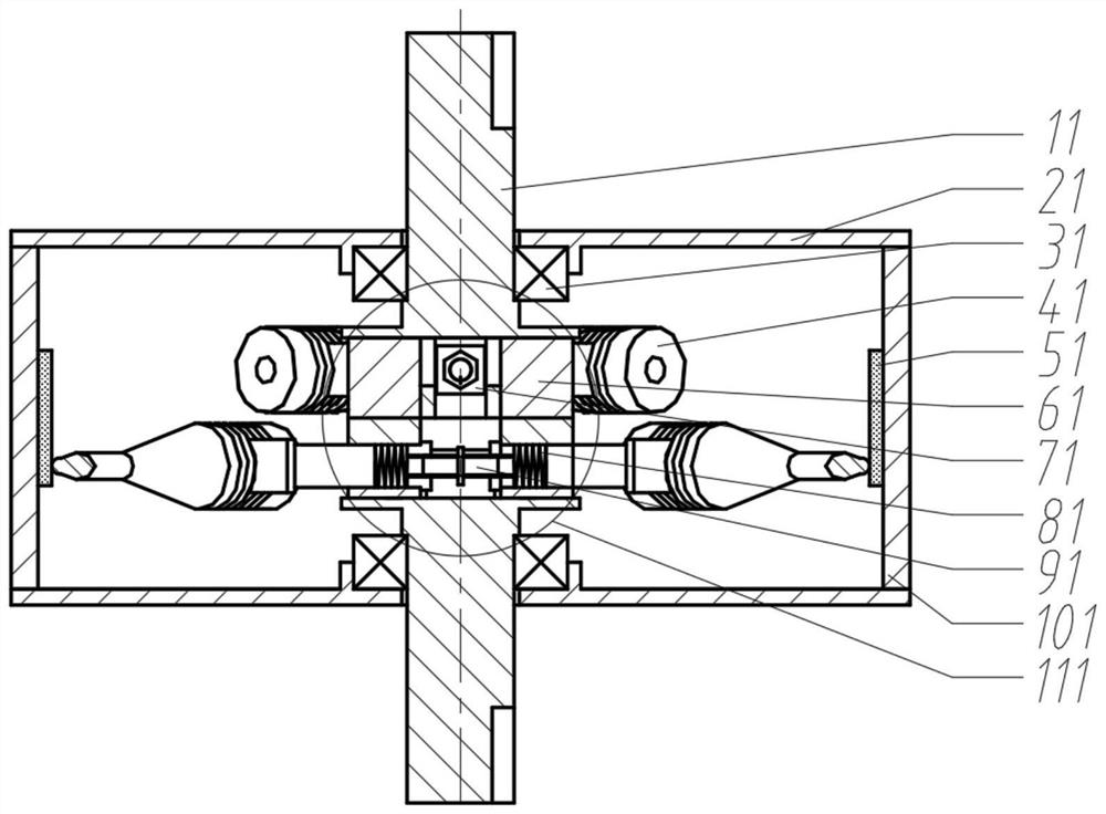
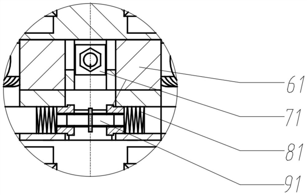
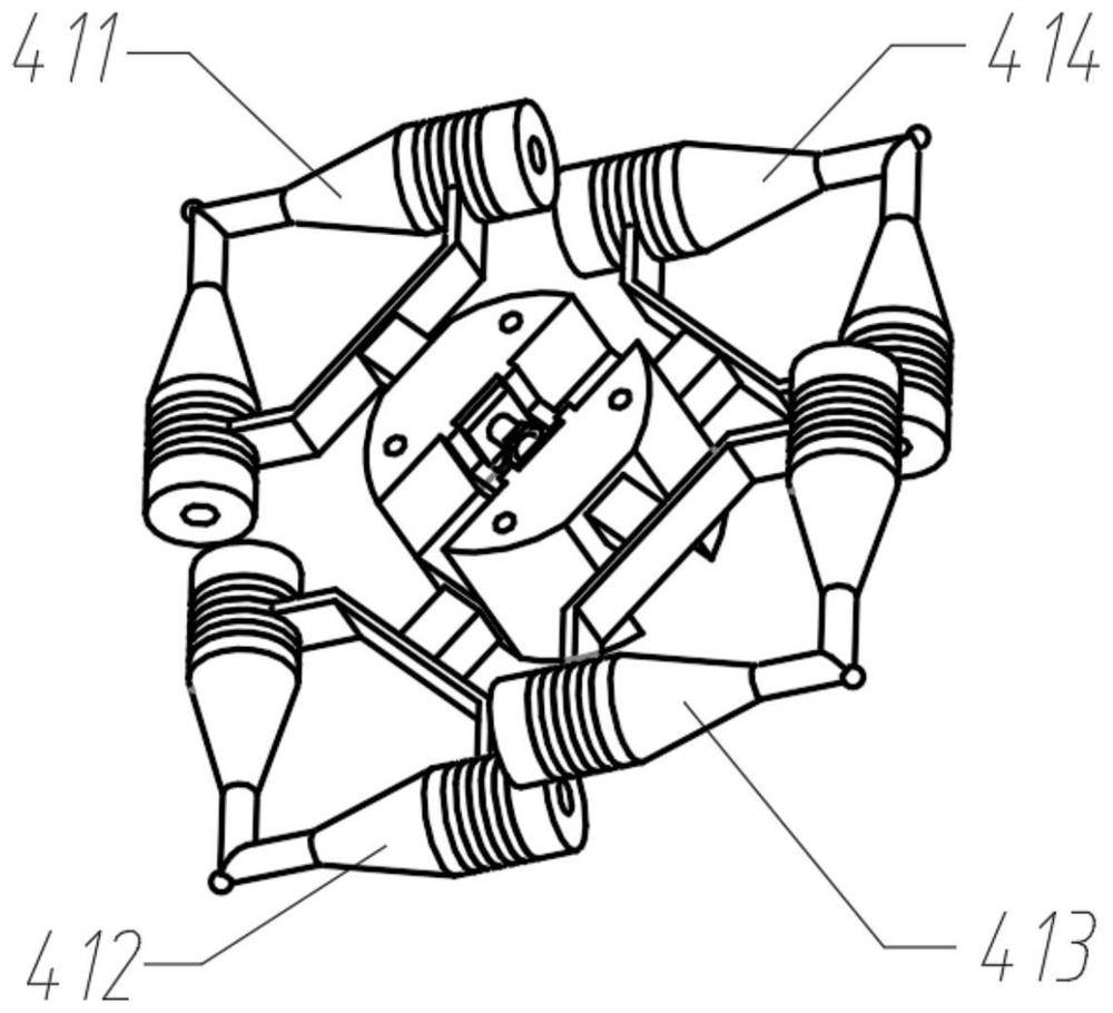
[0035] In this embodiment, the four V vibrators do not generate driving force at the same time. When the upper two V vibrator contacts contact the friction layer to generate driving force, the lower two V vibrator contacts do not contact the friction layer, and vice versa. If the phase difference of the two-phase excitation signals of V vibrator A and B is adjusted to -90°, the reverse rotation of the motor can be realized. Such as image 3 The four V vibrators of the rotor are shown, and the two sandwich transducers of each V vibrator are divided into two phases, A and B, as shown in Figure 6 As shown, in this embodiment, (411), (413) oscillators A and B phases are connected to simple harmonic excitation signals with a phase difference of 90°, and (412), (414) oscillators A phases are connected to (414) The phase difference of phase A of No. (413) vibrator is 180° simple harmonic excitation signal, and the phase difference of phase B of No. (412) and No. (414) vibrator conn...

Embodiment 2

[0037]In this embodiment, the four V oscillators generate driving force at the same time, and the excitation signal of each V oscillator is completely the same, that is, the same frequency and the same phase. If the phase difference of the two-phase excitation signals of V vibrator A and B is adjusted to -90°, the reverse rotation of the motor can be realized. Such as image 3 The four V oscillators of the shown rotor, (411), (412), (413), and (414) oscillators A and B are connected to simple harmonic excitation signals with a phase difference of 90°.

Embodiment 3

[0039] In this embodiment, by changing the angle between the two sandwich transducers of the V vibrator, the contact of the V vibrator can be controlled to form an elliptical motion. When the included angle is less than 90°, the ellipse formed by the V vibrator contact is prolate, such as Figure 7 As shown in (a), (72) is the movement track of the contact, which is oblong and elliptical, and the normal direction of the contact between the contact and the friction layer has a large amplitude, so when the contact and the friction layer rub against each other, a large friction force can be generated , so that the output torque of the motor is large.


PUM


Abstract

The invention discloses a parallel compound double output shaft rotary ultrasonic motor, which comprises: a base (61), which is used for installing a V vibrator, a pre-pressure mechanism and an output shaft; four V vibrators (41); Two preload bolts (91); four sleeves (71) that match the preload bolts; four springs (81); two shafts (11); two bearings (31); two end covers (21 ); a shell (101); there is a friction material layer in the shell, which is the friction layer (51). The motor makes an elliptical motion through the contact of the V vibrator, which rubs against the friction layer to generate a driving force. The principle and structure of the invention are simple, and the rotating electrical machine has the characteristics of large output torque, good running stability and the like.

Description

technical field [0001] The invention relates to an ultrasonic motor, in particular to a rotating ultrasonic motor designed by connecting V vibrators in parallel, and belongs to the field of ultrasonic motors. Background technique [0002] Compared with traditional electromagnetic motors, ultrasonic motors do not rely on electromagnetic media to transmit energy, but use the inverse piezoelectric effect of piezoelectric ceramics to convert and couple different vibration modes (stretching / bending / torsion) to transform the microscopic deformation of materials Through resonance amplification and frictional coupling, it is transformed into the macro motion of the vibrator or slider, and the motor is not easily disturbed by the electromagnetic field when it is working. At present, most rotary ultrasonic motors have the defect that the output torque is not large. The V-shaped linear ultrasonic motor designed based on the Langevin vibrator has the advantage of large thrust. If the V ...

Claims


Application Information

Patent Timeline
Patent Type & Authority Patents(China)
IPC IPC(8): H02N2/12H02N2/10
CPCH02N2/103H02N2/12
Inventor 李志宝张彦虎袁项辉周玉华全力
Owner JIANGSU UNIV
Why Eureka
Try Eureka