Method for adjusting the rotational speed of a centrifugal pump

A centrifugal pump, speed technology, applied in pump control, non-variable-capacity pumps, machines/engines, etc., to solve problems such as adjustment that cannot lead to satisfactory results, tedious adjustment outdated, and changes in mathematical relationships.

Active Publication Date: 2021-05-25
KSB AG
View PDF0 Cites 0 Cited by
  • Summary
  • Abstract
  • Description
  • Claims
  • Application Information

AI Technical Summary

Problems solved by technology

These regulator types are durable, especially under different operating conditions, and render obsolete the previously discussed tedious adjustment of regulator parameters
But a disadvantageous limitation of this type of regulator is that they can currently only be used in closed hydraulic circuits
For open loops that sometimes overcome geodesic heights, the mathematical relationship between the parameters changes and adjustments do not lead to satisfactory results

Method used


Image

  • Method for adjusting the rotational speed of a centrifugal pump
  • Method for adjusting the rotational speed of a centrifugal pump
  • Method for adjusting the rotational speed of a centrifugal pump

Examples


Embodiment Construction
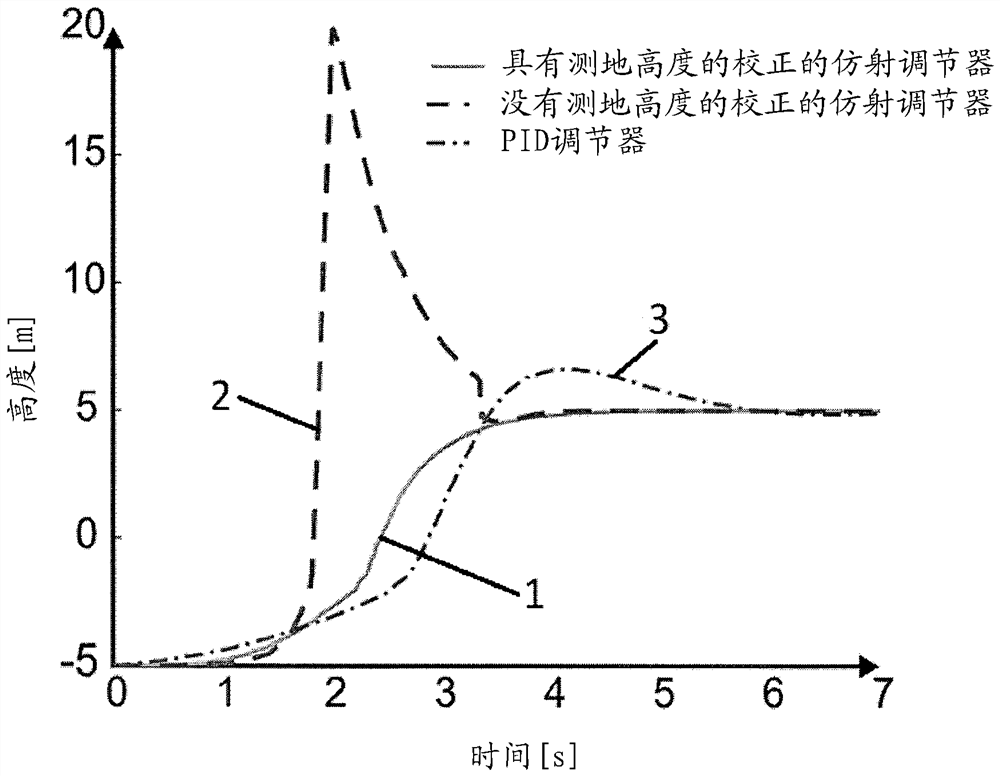
[0024] The core idea of ​​the invention is to use a new type of regulator for speed regulation of a centrifugal pump. Unlike the prior art, it is proposed not to use a PI or PID controller at all, but instead to use a so-called affine controller, which uses the affine law to determine the manipulated value / target value and is therefore based on the rotational speed of the centrifugal pump Power of two relationship with the resulting delivery height.

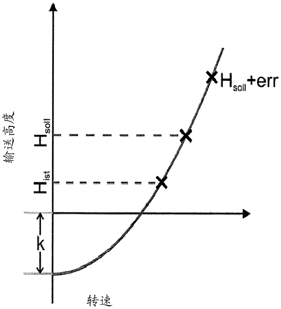
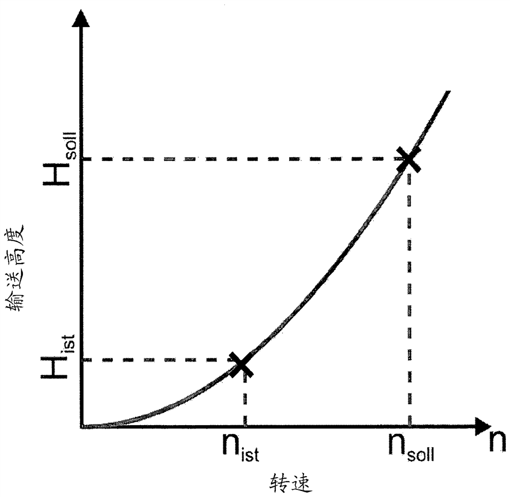
[0025] For a description of the functionality of this affine regulator, see figure 1 . The delivery height is plotted against the set pump rotational speed in the diagram representation. The diagram shows here in detail the quadratic relationship between the conveying height H and the rotational speed n, which can be expressed by the equation

[0026] (Equation 1)

[0027] to describe. also, figure 1 exemplarily shows the actual-rotational speed n ist and target-speed n soll . Due to the relationship of the second pow...


PUM


Abstract

The invention relates to a method for regulating the rotational speed of a centrifugal pump operated in an open hydraulic circuit, wherein a controller of the pump control is calculated taking into account the target-delivery height and the actual-delivery height and the actual-rotational speed A target rotational speed of the pump drive, wherein the controller takes into account the correction parameter describing the geodetic altitude for the calculation of the target rotational speed.

Description

technical field [0001] The invention relates to a method for regulating the rotational speed of a centrifugal pump operated in an open hydraulic circuit, wherein a controller of the pump control is determined taking into account the target delivery height and the actual delivery height as well as the actual rotational speed Target - rotational speed of the pump drive. Background technique [0002] Today's speed-regulated centrifugal pumps of the prior art mainly use PI controllers for determining the target speed. With the P-part it is possible to determine how quickly the pump reaches its target value. With the help of the I-part, it is possible to adjust how residual dynamic control deviations are to be eliminated. When the I-part is zero, there is always a residual control error remaining. [0003] Since the configuration of the two regulator parameters affects the dynamics of the overall system, the adjustment of the regulator parameters cannot be carried out individu...

Claims


Application Information

Patent Timeline
Patent Type & Authority Patents(China)
IPC IPC(8): F04D15/00
CPCF04D15/0066F04D15/00
Inventor M.埃克尔J.舒莱雷尔
Owner KSB AG
Why Eureka
Try Eureka