
Material issuing device of high-speed checkweigher

A checkweigher, high-speed technology, applied in the direction of conveyor control devices, packaging, transportation and packaging, etc., can solve the problems of low stability and low production efficiency of bottle-shaped workpieces

Active Publication Date: 2019-10-29
上海实干实业有限公司
View PDF6 Cites 0 Cited by
  • Summary
  • Abstract
  • Description
  • Claims
  • Application Information

AI Technical Summary

Problems solved by technology

[0005] For this reason, the embodiment of the present invention provides a high-speed checkweigher delivery device to solve the problems of backturning and low production efficiency in the prior art due to the low stability of the bottle-shaped workpiece during the speed-up conveying process

Method used


Image

  • Material issuing device of high-speed checkweigher
  • Material issuing device of high-speed checkweigher
  • Material issuing device of high-speed checkweigher

Examples


Embodiment 1

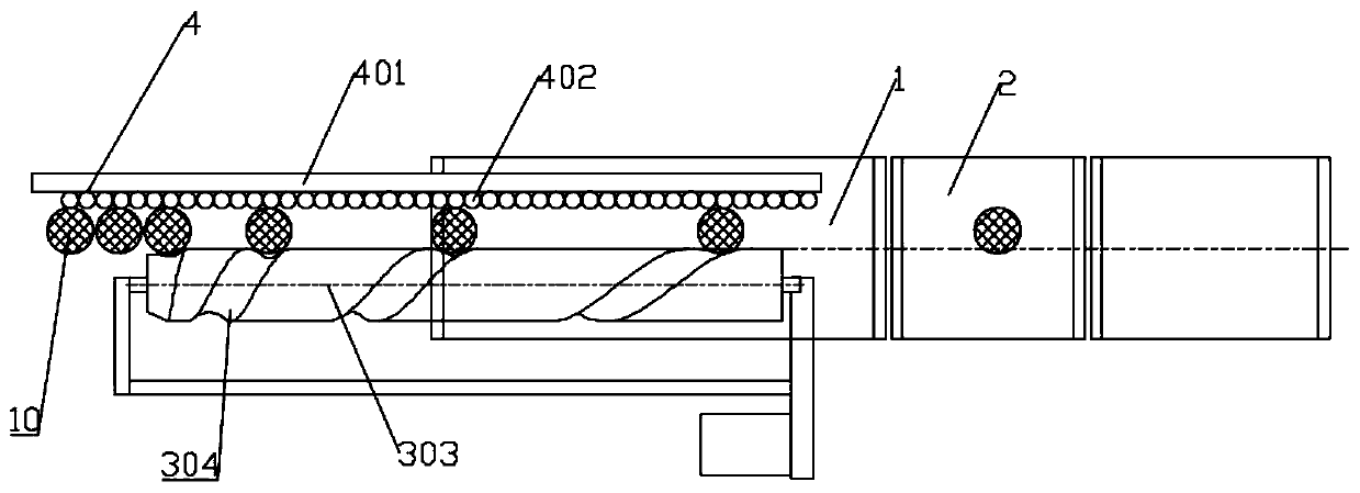
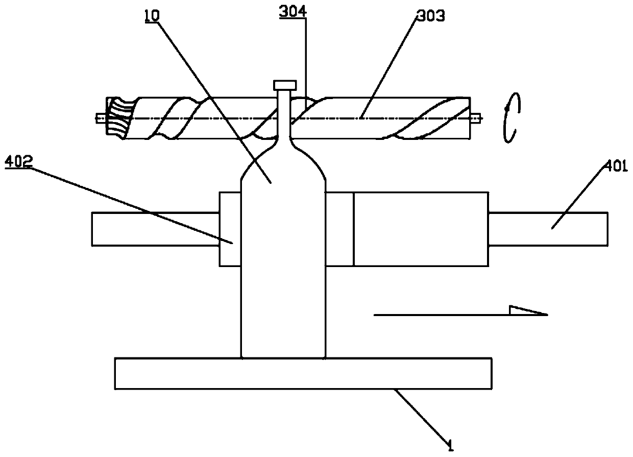
[0045] Such as figure 2 with image 3 As shown, the first clamping assembly 4 for limiting the side wall of the bottle-shaped workpiece 10 is provided parallel to the conveying direction of the front end conveyor 1 . Specifically: the first clamping assembly 4 includes a clamping support frame 401 , which is arranged parallel to the conveying direction of the front end conveyor 1 and distributed on one side of the conveying direction of the bottle-shaped workpiece 10 . It is used to prevent the bottle-shaped workpiece 10 from moving sideways and rotates with the screw rod 303 .

[0046] In order to reduce the friction between the bottle-shaped workpiece 10 and the clamping support frame 401, the clamping support frame 401 is provided with a conveying roller 402 set towards the conveying direction of the front end conveyor 1, and the sliding friction in contact between the two is changed into rolling friction , Reduce wear on the surface of the bottle-shaped workpiece 10.

...

Embodiment 2

[0049] Such as Figure 4 As shown, an indirect contact assembly 5 is movably connected to the variable-pitch helical groove 304. The indirect contact assembly 5 includes a wear-resistant limiting plate 501 for limiting the bottle-shaped workpiece 10. The wear-resistant limiting plate 501 can prevent the bottle-shaped workpiece from 10 rollovers. The wear-resistant limiting plate 501 is provided with a rolling clamp for clamping inside the variable-pitch helical groove 304 . The rolling clip can make the wear-resistant limiting plate 501 slide smoothly on the surface of the screw rod 303 .

[0050] Preferably, the rolling clamp is a universal wheel 502 , and the cross section of the variable-pitch helical groove 304 matches the universal wheel 502 .

[0051] The sidewalls at both ends of the wear-resistant limiting plate 501 are limited by the second clamping assembly 503, and the second clamping assembly 503 can prevent the wear-resistant limiting plate 501 from rotating dur...


PUM


Abstract

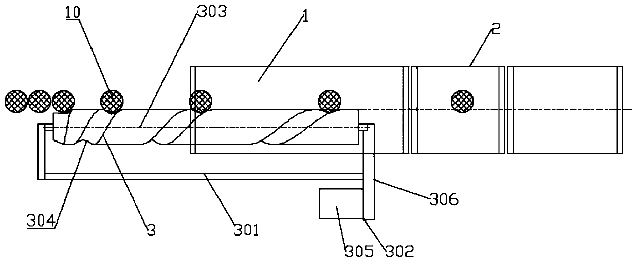
The embodiment of the invention discloses a material issuing device of a high-speed checkweigher. The material issuing device of the high-speed checkweigher comprises a front-end conveyor and a weighing conveyor for weighing a bottle-shaped workpiece conveyed by the front-end conveyor, wherein a differential material stabilizing device for preventing the bottle-shaped workpiece from side turning in the speed-changing conveying process is arranged on one side of the front-end conveyor; the differential material stabilizing device comprises an installation support; a screw rod arranged parallelto a conveying direction of the front-end conveyor and driven by a power device so as to rotate is arranged on the installation support; a variable-pitch spiral groove is formed in the screw rod; andthe bottle-shaped workpiece is limited by the variable-pitch spiral groove and moves linearly along with the variable-pitch spiral groove along the conveying direction of the front-end conveyor. According to the material issuing device of the high-speed checkweigher provided by the invention, the differential material stabilizing device capable of synchronously conveying the bottle-shaped workpiece and the front-end conveyor is additionally arranged above the front-end conveyor, and the speed of the bottle-shaped workpiece gradually stays the same with the linear speed of the front-end conveyor under the clamping of the variable-pitch spiral groove on the screw rod, so that bottles are conveyed stably.

Description

technical field [0001] The embodiments of the present invention relate to the technical field of material sending devices, and in particular to a material sending device of a high-speed checkweigher. Background technique [0002] Sending out materials is a common process in industrial production. Due to the popularity of mechanized production, sending out materials has also changed from the original manual sending out to more efficient and stable mechanical sending out. In today's increasingly fierce market competition, various production enterprises urgently need to improve production technology and increase production efficiency. Especially in the material delivery stage, improvements are made to reduce the original low production efficiency, high production cost and unstable material delivery. Sending materials is sometimes not only feeding, but also has the function of intermittent feeding and distribution. The automatic sending device has been used in the production p...

Claims


Application Information

Patent Timeline
Patent Type & Authority Applications(China)
IPC IPC(8): B65G43/08B65G37/00B65G47/22B65G33/04B65G33/34B65G33/26
CPCB65G33/04B65G33/26B65G33/34B65G37/00B65G43/08B65G47/22B65G2201/0244B65G2203/0258
Inventor 周建珍
Owner 上海实干实业有限公司
Learn More