Automatic feeding and discharging device based on digital control drilling machine for circuit board
A technology of automatic loading and unloading, CNC drilling machine, applied in positioning device, feeding device, boring/drilling, etc., can solve problems such as low efficiency, and achieve low efficiency, stable conveying, and prevention of offset jamming Effect
- Summary
- Abstract
- Description
- Claims
- Application Information
AI Technical Summary
Problems solved by technology
Method used
Image
Examples
Embodiment 1
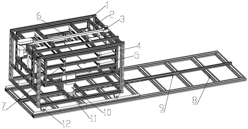
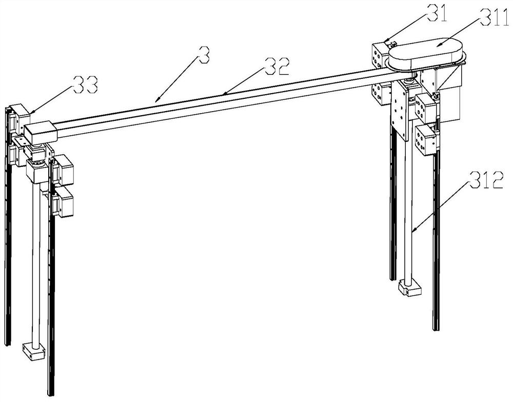
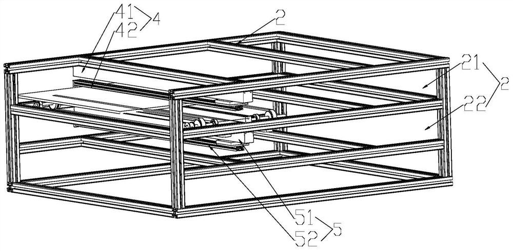
[0026] Embodiment one: as attached Figure 1-4As shown, the present invention discloses an automatic loading and unloading device based on a circuit board numerical control drilling machine, which includes a frame 1, a lifting unit 3, a support frame 2, a pushing unit 4, a pulling unit 5, a conveying unit Unit 6 and anti-deflection guide bar 7; wherein, the lifting unit 3 is fixedly arranged on the frame 1, the support frame 2 is fixedly arranged on the moving end of the lifting unit 3, and the conveying unit 6 is transversely Fixedly arranged on the support frame 2, the anti-deflection guide bar 7 is fixed laterally on the support frame 2 and kept at the same level as the moving end of the conveying unit 6 so that the circuit board is driven by the conveying unit 6 Move along the direction of the anti-deflection guide bar 7, and the pull-back unit 5 is fixed laterally on the support frame 2 above the conveying unit 6 so that the circuit board is driven by the pull-back unit 5...
Embodiment 2
[0031] Embodiment two: as attached Figure 1-4 As shown, the present invention discloses an automatic loading and unloading device based on a circuit board numerical control drilling machine. The automatic loading and unloading device based on a circuit board numerical control drilling machine also includes a base 8, a moving motor 10, a moving rack 9 and Mobile gear 11; the mobile rack 9 is fixedly arranged on the base 8, the mobile motor 10 is fixed on the bottom of the frame 1 and the drive shaft of the mobile motor 10 is provided with the mobile rack The moving gear 11 meshed with 9 makes the frame 1 move along the moving rack 9 driven by the moving motor 10 . In the embodiment of the present invention, the moving rack 9 is welded and fixed on the middle position of the base 8 horizontally, and the moving motor 10 is welded and fixed on the bottom of the frame 1 and the moving motor 10 The drive shaft is provided with a moving gear 11 meshed with the moving rack 9 . In t...
Embodiment 3
[0032] Embodiment 3: The present invention discloses an automatic loading and unloading device based on a circuit board numerical control drilling machine. Wherein, the push-in unit 4 also includes a push-in motor and a push-in screw; the push-in motor is fixed on the support frame 2 above the conveying unit 6, and one end of the push-in screw is fixed on the On the drive shaft of the push-in motor, the push-in cylinder 41 is threadedly arranged on the other end of the push-in screw rod so that the push-in cylinder 41 is pushed in vertically along the push-in screw rod under the drive of the push-in motor. Activity. In the embodiment of the present invention, when the present invention is powered on, the conveying unit 6 is fixed laterally on the support frame 2 so that the circuit board is driven by the conveying unit 6 to open along the support frame 2, that is, along the The direction of the anti-deflection guide bar 7 makes the leftmost end of the circuit board move to th...
PUM
 Abstract
Description
Claims
Application Information
 - R&D
- Intellectual Property
- Life Sciences
- Materials
- Tech Scout
- Unparalleled Data Quality
- Higher Quality Content
- 60% Fewer Hallucinations
Browse by: Latest US Patents, China's latest patents, Technical Efficacy Thesaurus, Application Domain, Technology Topic, Popular Technical Reports.
© 2025 PatSnap. All rights reserved.Legal|Privacy policy|Modern Slavery Act Transparency Statement|Sitemap|About US| Contact US: help@patsnap.com


