A Reliable Hub Chuck

A kind of hub and reliable technology, which is applied in the field of machine manufacturing, can solve the problems of complex movement trajectories of the jaws, increase the outer size of the chuck, and low reliability of loading, unloading and opening, and achieves reduced range of motion, reduced weight, and good rigidity. Effect

Active Publication Date: 2021-03-30
NINGBO DEMA INTELLIGENT MACHINERY CO LTD
View PDF15 Cites 0 Cited by
  • Summary
  • Abstract
  • Description
  • Claims
  • Application Information

AI Technical Summary

Problems solved by technology

[0002] The automobile hub is a cylindrical metal part used to support the tire. The main processing method is to fix the semi-finished product of the hub on the chuck fixture, and then turn the outer and inner sides of the hub. The chuck of the general lathe is mainly along the diameter of the chuck. To clamp the workpiece, excessive clamping force will clamp and deform the hub. In order to eliminate the damage of the clamp to the hub, the prior art provides a chuck that prevents the deformation of the hub, which includes a chuck base, a pull plate and The jaws clamp the hub axially, avoiding the radial deformation of the hub, but the jaws are rotatably connected to the pull plate, and the pull plate drives the claws to reciprocate in the axial direction, which not only increases the axial movement of the entire chuck The size is upward, and the movement trajectory of the entire jaw is complex, and the opening and closing reliability of the jaw is low. In order to ensure that the jaw moves according to the preset trajectory, a complex connection structure needs to be added to the chuck base to cooperate with the jaws, which not only increases the The weight of the chuck increases the overall size of the entire chuck, and the reliability of loading and unloading is low.

Method used


Image

  • A Reliable Hub Chuck
  • A Reliable Hub Chuck
  • A Reliable Hub Chuck

Examples


Embodiment Construction

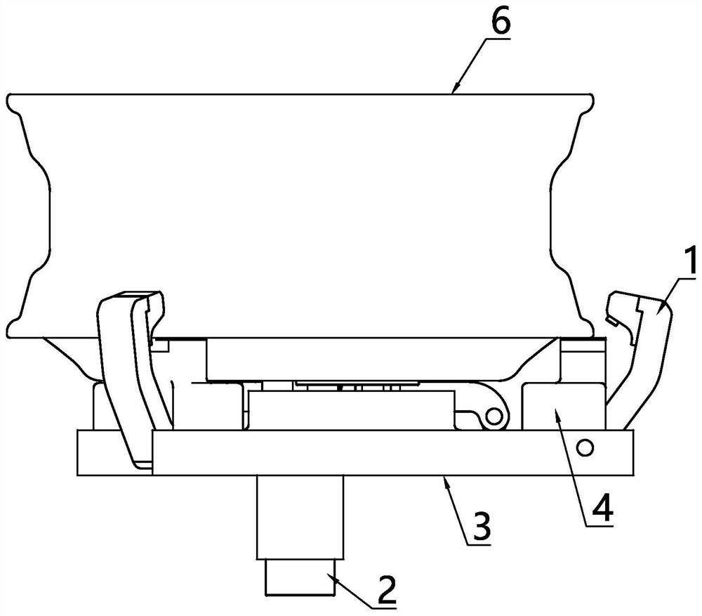
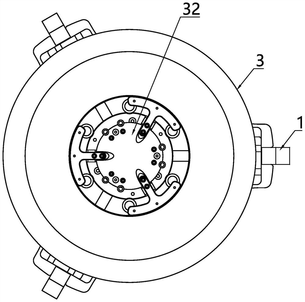
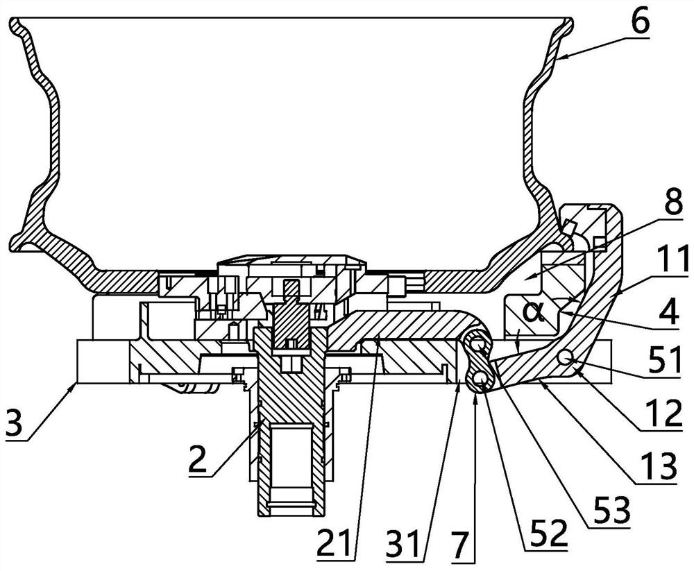
[0021] The present invention provides a reliable hub chuck such as Figure 1 to Figure 4 As shown, it includes a claw 1 and a moving sleeve 2 with a moving rod 21. The driving device drives the moving sleeve 2 to reciprocate along the axis of the main shaft. The outer sleeve of the moving sleeve 2 is provided with a base plate 3 that rotates synchronously with the main shaft. An end face locator 4 for the axial positioning of the hub 6 is provided, and the claw 1 includes a gripping arm 11, a connecting arm 13 and a connecting portion 12 connecting the gripping arm 11 and the connecting arm 13, and the gripping arm 11 compresses the wheel hub 6 on the The hub 6 is clamped on the end surface positioning member 4 , the connecting portion 12 is hinged to the base plate 3 through the first rotating shaft 51 , and the connecting arm 13 is movably connected to the moving rod 21 .

[0022] The reciprocating moving sleeve 2 drives the grasping arm 11 to rotate around the first rotatin...


PUM


Abstract

The invention discloses a reliable hub chuck, and solves the problem that the motion track of a clamping jaw is complex and the opening and closing reliability is low. According to the technical scheme, the reliable hub chuck mainly comprises the clamping jaw and a moving sleeve with a moving rod, wherein a driving device drives the moving sleeve to move in the axial direction of a main shaft in areciprocating mode, a base plate which synchronously rotates along with the main shaft is arranged on the outer side of the moving sleeve in a sleeved mode and is provided with an end face positioning piece used for axially positioning a hub, the clamping jaw comprises a grasping arm, a connecting arm and a connecting part which connects the grasping arm with the connecting arm, the hub is tightly pressed on the end surface positioning piece through the grasping arm so as to clamp the hub, the connecting part is hinged to the base plate through a first rotating shaft, a middle rod is arrangedbetween a moving rod and the connecting arm, one end of the middle rod is hinged to the connecting arm through a second rotating shaft, the other end of the middle rod is hinged to the moving rod through a third rotating shaft, the center distance of the first rotating shaft and the second rotating shaft is L1, the center distance of the second rotating shaft and the third rotating shaft is L2, the center distance of the first rotating shaft and the third rotating shaft is L3, and the following condition is met: L1 plus L2 is greater than L3.

Description

technical field [0001] The invention relates to the technical field of machine manufacturing, in particular to a reliable hub chuck. Background technique [0002] The automobile hub is a cylindrical metal part used to support the tire. The main processing method is to fix the semi-finished product of the hub on the chuck fixture, and then turn the outer and inner sides of the hub. The chuck of the general lathe is mainly along the diameter of the chuck. To clamp the workpiece, excessive clamping force will clamp and deform the hub. In order to eliminate the damage of the clamp to the hub, the prior art provides a chuck that prevents the deformation of the hub, which includes a chuck base, a pull plate and The jaws clamp the hub axially, avoiding the radial deformation of the hub, but the jaws are rotatably connected to the pull plate, and the pull plate drives the claws to reciprocate in the axial direction, which not only increases the axial movement of the entire chuck Th...

Claims


Application Information

Patent Timeline
Patent Type & Authority Patents(China)
IPC IPC(8): B23B31/16B23B31/103B23B31/24
CPCB23B31/103B23B31/16B23B31/24
Inventor 董祥义李文龙
Owner NINGBO DEMA INTELLIGENT MACHINERY CO LTD
Why Eureka
Try Eureka