AGV with clamping and holding mechanism and butt joint method thereof

A technology for docking components and clamping arms, which is used in traction connectors, transportation and packaging, vehicle components, etc., which can solve the problem of increasing the uncertainty of the feeder, the inability to guarantee the stopping accuracy, and increasing the difficulty of docking the feeder with the next station, etc. problems, to achieve the effect of improving driving accuracy and stopping accuracy, preventing left and right swing, and avoiding shaking

Pending Publication Date: 2019-11-01
GUANGDONG JATEN ROBOT & AUTOMATION
0 Cites 1 Cited by

AI-Extracted Technical Summary

Problems solved by technology

[0002] In the automatic production line workshop, the AGV with navigation function is usually used to transport materials. The specific operation is to dock the AGV with the material truck, and then drive the material truck to the designated place. However, the AGV has driving and stopping accuracy, and the AGV and the material When the car is docked, it is necessary to leave a docking allowance. Only rely...

Abstract

The invention provides an AGV with a clamping and holding mechanism and a butt joint method thereof. The AGV comprises an AGV body, a butt joint assembly and a clamping and holding mechanism; the buttjoint assembly is used for being in butt joint with a butt joint mechanism on a material vehicle, and is used for providing traction to the material vehicle; the clamping and holding mechanism is arranged on the AGV body; the clamping and holding mechanism comprises a telescopic component and two groups of clamping arm components; the telescopic component is arranged on the AGV body; the clampingarm components are arranged on the telescopic component; and when the AGV is in butt joint with the material vehicle, the two groups of clamping arm components extend out of the two sides of the material vehicle along with the telescopic component and are used for limiting the swinging amplitude of the material vehicle in the left-and-right direction. According to the AGV, the clamping and holding mechanism is additionally arranged on the AGV body, the left side and the right side of the material vehicle are clamped through the clamping arm components, the constraint is added to the left andright directions of the driving direction of the material vehicle, the material vehicle can be prevented from swinging left and right, and the running precision and the stopping precision of the material vehicle are improved.

Application Domain

Technology Topic

Image

  • AGV with clamping and holding mechanism and butt joint method thereof
  • AGV with clamping and holding mechanism and butt joint method thereof
  • AGV with clamping and holding mechanism and butt joint method thereof

Examples

  • Experimental program(1)

Example Embodiment

[0032] Hereinafter, a preferred embodiment of the present invention will be described with reference to the accompanying drawings.
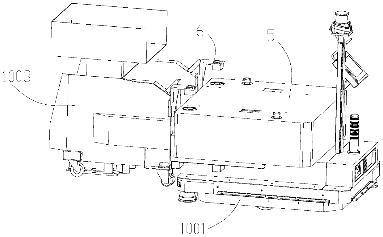
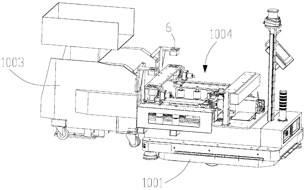
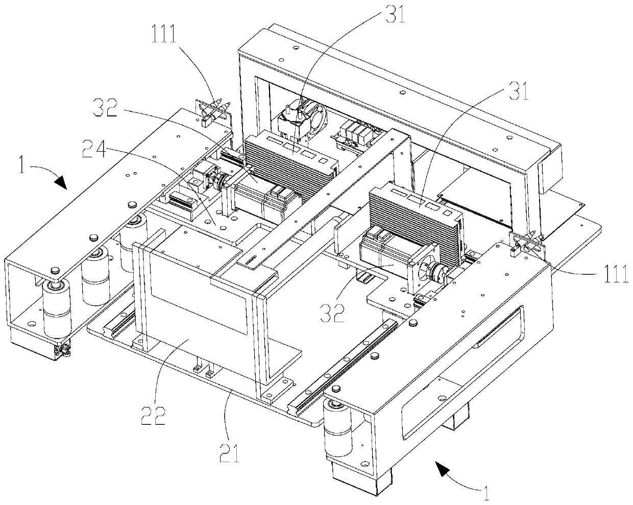
[0033] See Figure 1 to Figure 10 , An AGV with a clamping mechanism, which includes an AGV body 1001, a docking assembly 1002, and a clamping mechanism 1004. The docking assembly 1002 is used for docking with the docking mechanism on the material cart 1003, and the clamping mechanism 1004 is arranged at On the AGV body 1001, the gripping mechanism 1004 includes a telescopic assembly 2 and two sets of gripping arm assemblies 1. The telescopic assembly 2 is arranged on the AGV body 1001, and the gripping arm assembly 1 is arranged on the telescopic assembly 2. Above, when the AGV is docked with the feeder 1003, the two sets of clamping arm assemblies 1 extend to the two sides of the feeder 1003 along with the telescopic assembly 2 to limit the left and right direction of the feeder 1003 The swing amplitude; wherein, the clamping mechanism 1004 also includes two sets of transverse transmission devices 3, the transverse transmission devices 3 are provided on the telescopic assembly 2, the clamp arm assembly 1 and the transverse transmission device 3Connect.
[0034] Compared with the prior art, the AGV provided by the present invention has a gripping mechanism 1004, which adds a gripping mechanism 1004 to the AGV body 1001, and separately controls the two gripping arm assemblies 1 and the material through two sets of transverse transmission devices. The contact of the trolley 1003 can realize the complete clamping of the feed trolley 1003. While the left and right directions of the feeding trolley 1003 are increased, restraints are added to prevent the feed trolley 1003 from overlapping the center line of the AGV. The emergence of a virtual position caused by the inconsistent clamping strokes required on both sides can avoid shaking of the feeder 1003 during driving, so that the feeder 1003 can follow the AGV with high precision.
[0035] See Figure 8 As a preferred solution, the traverse transmission device 3 includes a driver 31, a drive motor 32, a transmission screw 33, a screw nut 34, a guide rail 35, and a first connecting plate 36 slidably arranged on the guide rail 35. The driver 31 drives the motor 32 to act. The drive motor 32 is in transmission connection with the transmission screw 33. The screw nut 34 is threadedly connected to the transmission screw 33. The screw nut 34 is arranged on the first connecting plate 36. On the lower end surface, the clamping arm assembly 1 is arranged on the upper end surface of the first connecting plate 36, and the first connecting plate 36 is connected to the guide rail 35 through the first sliding block 37, and its structure is simple and reliable. In this embodiment, there are two guide rails 35 of each traverse transmission device 3, which are respectively provided on both sides of the lower end surface of the first connecting plate 36.
[0036] See Figure 7 As a preferred solution, the clamp arm assembly 1 includes an upper pallet 11 and a lower pallet 12. The upper pallet 11 and the lower pallet 12 are connected by a second connecting plate 13, and the lower side of the upper pallet 11 is connected to the screw rod The nut 34 is fixedly connected. A number of bearing wheels 14 are provided between the upper pallet 11 and the lower pallet 12. The bearing wheels 14 limit the position of the feeder 1003. At the same time, the AGV and the feeder When the front and rear directions of 1003 are switched, due to the margin of the docking assembly 1002 and the docking mechanism of the feeder 1003, the feeder 1003 and the clamping arm will be misaligned, and the bearing wheel 14 can perfectly prevent the surface of the feeder 1003 from scratching. In this embodiment, the upper supporting plate 11, the lower supporting plate 12 and the second connecting plate 13 are integrated.
[0037] See Figure 4 with Figure 7 As a preferred solution, each of the two sets of clamping arm assemblies 1 is provided with a travel switch 15, the travel switch 15 is fixed on the lower side of the lower support plate 12, and the end of the upper support plate 11 is fixed with a first approach Switch 111, the travel switch 15 can be used to detect that the clamp arm assembly 1 clamps the material cart 1003 and then stops moving. The first proximity switch 111 is used to limit the clamp arm assembly 1, which respectively ensures that the clamp arm assembly 1 returns when retracted. To the initial position.
[0038] See Figure 4 with Figure 7 As a preferred solution, there are two travel switches 15 on the clamp arm assembly 1, which are respectively provided on the lower side of the front and rear ends of the lower pallet 12. Each clamp arm assembly 1 is provided with two travel switches 15 to prevent The non-parallel relationship between the feeder 1003 and the gripper arm assembly 1, that is, if the gripper arm assembly 1 and the feeder 1003 are relatively inclined, the contact of the gripper arm while the travel switch 15 is not contacted can be avoided to ensure the gripping The arm assembly 1 stops in place.
[0039] It should be noted that since the contact part between the clamp arm and the feed cart 1003 is usually the front end of the clamp arm assembly 1, the length of the lower pallet 12 in the clamp arm assembly 1 can be designed to be less than the length of the upper pallet 11. On the one hand, it can save the number of bearing wheels 14 and save costs. On the other hand, it can ensure that the relative distance between the two travel switches 15 on the clamp arm assembly 1 is small, which enhances the contact between the clamp arm assembly 1 and the feeder 1003. Induction intensity.
[0040] See Figure 3 to Figure 6 As a preferred solution, the telescopic assembly 2 includes a bottom plate 21, a bracket 22, an electric push rod 23, a mounting plate 24, a first linear slide 25 and a second sliding block 26, and the fixed end of the electric push rod 23 is fixed The bracket 22 is fixed on the bottom plate 21, the telescopic end of the electric push rod 23 is fixedly connected to the mounting plate 24 through the long plate assembly 29, and the transverse transmission device 3 is fixed on the mounting plate 24, the first linear slide 25 is fixed on the bottom plate 21, the second slider 26 is movably provided on the first linear slide 25, and the mounting plate 24 is connected to the first linear slide. The slide rail 25 is fixedly connected, and the expansion and contraction of the electric push rod 23 drives the mounting plate 24 to move back and forth, thereby driving the extension and retraction of the clamp arm assembly 1. The structure is simple and the cost is low. In this embodiment, there are two first linear slide rails 25, which are respectively provided on both sides of the electric push rod 23, and each first linear slide rail 25 is provided with two second slide rails. Block 26, the bracket 22 is fixedly connected to the bottom plate 21 through a right-angled plate 28 to enhance the stability of the bracket 22. The two traverse transmission devices 3 are fixedly connected to the mounting plate 24 through two third connecting plates 27, and the transmission screw 33 and the guide rail 35 are both fixedly arranged on the third connecting plate 27.
[0041] See Figure 4 As a preferred solution, the front end side of the electric push rod 23 is provided with a second proximity switch 231, and the rear end side of the electric push rod 23 is provided with a third proximity switch 232, the second proximity switch 231 and The third proximity switch 232 is fixed on the bottom plate 21, and the second proximity switch 231 and the third proximity switch 232 are fixed on the bottom plate 21. The second proximity switch 231 and the third proximity switch 232 give the clamp arm The maximum and minimum telescopic positions are set with safety signals to prevent overruns and ensure the safe operation of the clamping mechanism 1004
[0042] See figure 1 As a preferred solution, in order to prevent dust and water, a cover 5 is further included, which is sleeved on the outside of the clamping mechanism 1004 and fixedly connected to the bracket 22.
[0043] See Figure 5 As a preferred solution, the docking assembly 1002 is configured to include a lifting pin 1021 and a third motor 1022, and the third motor 1022 drives the lifting pin 1021 to engage with the lifting pin guide seat 6 on the material truck 1003. In the embodiment There are two docking assemblies 1002, which are respectively fixed on both sides of the bracket 22 through a third connecting plate 1023, and the third connecting plate 1023 is fixedly connected to the upper side of the bracket 22.
[0044] See Figure 4 As a preferred solution, in order to make the work of the clamping mechanism 1004 more stable and reliable, a counterweight 4 is provided on the bottom plate 21 at the rear end of the clamping arm assembly 1 to balance the weight of the clamping mechanism 1004.
[0045] See Figure 1 to Figure 10 The present invention also provides a method for docking an AGV with the above-mentioned clamping mechanism 1004, wherein the AGV with the above-mentioned clamping mechanism 1004 further includes a control module for controlling the clamping arm assembly 1, the docking assembly 1002 and the movement of the telescopic assembly 2, the docking method includes the following steps:
[0046] a. After receiving the docking and transportation task, the AGV with the gripping mechanism 1004 drives to the docking station with the material truck 1003,
[0047] The control module on the gripping mechanism 1004 controls the extension of the lifting pin, which extends into the lifting pin guide seat of the material cart 1003, and the lifting pin is extended in position signal is triggered;
[0048] b. The electric push rod 23 in the clamping mechanism 1004 works, and the telescopic assembly 2 is driven to drive the clamping arm assembly 1 to extend, and the two sets of clamping arm assemblies 1 of the clamping arm assembly 1 extend into the area of ​​the feeder 1003 until the second proximity switch 231 senses Stop action after;
[0049] c. The two drive motors 32 respectively drive the two clamping arms to approach both sides of the material cart 1003. When the travel switches 15 provided on the two clamping arms are triggered respectively, the corresponding clamping arms stop moving and keep the material The trolley 1003 touches to realize clamping on the left and right sides of the material trolley 1003
[0050] d. After the AGV drives the feeder 1003 to the designated location through the gripping mechanism 1004, the motor-driven transmission screws 33 of the two traverse transmission devices 3 respectively drive the two groups of gripping arm assemblies 1 to retract in the direction of the unwinding of the feeder 1003. Stop the action until the two first proximity switches 111 are sensed;
[0051] e. After the two sets of clamping arm assemblies 1 are retracted and stopped, the electric push rod 23 in the clamping mechanism 1004 acts to drive the two sets of clamping arm assemblies 1 to retract until the third proximity switch 232 is sensed and then stops, making the clamping arm assembly 1 Return to the initial position
[0052] f. After the electric push rod 23 stops, the control module controls the lift pin 1021 to extend and retract, cancel the restraint relationship between the clamping mechanism 1004 and the material cart 1003, release the docking, and the AGV waits for the next docking and transportation task.
[0053] Compared with the prior art, compared with the prior art, the invention provides an AGV docking method with a gripping mechanism 1004, which uses two traverse transmission devices 3 to separately control the two sets of gripping arm assemblies 1 to the feeding cart The clamping of 1003 increases the constraints in the left and right directions of the feeder 1003's traveling direction, and at the same time prevents the inconsistency of the clamping strokes required on both sides of the feeder 1003, which leads to virtual errors when the center lines of the feeder 1003 and the AGV do not overlap. The emergence of the position avoids shaking of the feeder 1003 during the driving process, so that the feeder 1003 can follow the AGV with high precision, and the feeder 1003 can have a certain posture when parking.
[0054] Based on the disclosure and teaching of the foregoing specification, those skilled in the art to which the present invention belongs can also make changes and modifications to the foregoing embodiments. Therefore, the present invention is not limited to the specific embodiments disclosed and described above, and some modifications and changes to the present invention should also fall within the protection scope of the claims of the present invention. In addition, although some specific terms are used in this specification, these terms are only for convenience of description and do not constitute any limitation to the present invention.

PUM

no PUM

Description & Claims & Application Information

We can also present the details of the Description, Claims and Application information to help users get a comprehensive understanding of the technical details of the patent, such as background art, summary of invention, brief description of drawings, description of embodiments, and other original content. On the other hand, users can also determine the specific scope of protection of the technology through the list of claims; as well as understand the changes in the life cycle of the technology with the presentation of the patent timeline. Login to view more.

Similar technology patents

Cup

Owner:陈鹏旭

Workbench for detecting shaft workpieces

PendingCN114769369AImprove stabilityPrevent swingingMetal-working feeding devicesPositioning devicesEngineeringPressure - action
Owner:CHANGZHOU GIKEN PRECISION CO LTD

Convenient-to-fix cutting device

InactiveCN107598610APrevent swingingCutting stabilityFeeding apparatusLarge fixed membersEngineeringDrive wheel
Owner:无锡宝威焊割设备有限公司

Two-axle bogie with locking function

ActiveCN106740957APrevent swingingPrevent vehicle from tipping overBogiesBogie-underframe connectionsVehicle frameEngineering
Owner:BAOJI CSR TIMES ENG MACHINERY

Desk lamp for students

InactiveCN102900992APrevent swingingIncreased physical burdenLighting elementsFree standingMusic playerEngineering
Owner:SUZHOU CUIZHI NEW TECH DEV

Classification and recommendation of technical efficacy words

  • Prevent swinging

Convenient-to-fix cutting device

InactiveCN107598610APrevent swingingCutting stabilityFeeding apparatusLarge fixed membersEngineeringDrive wheel
Owner:无锡宝威焊割设备有限公司

Two-axle bogie with locking function

ActiveCN106740957APrevent swingingPrevent vehicle from tipping overBogiesBogie-underframe connectionsVehicle frameEngineering
Owner:BAOJI CSR TIMES ENG MACHINERY

Desk lamp for students

InactiveCN102900992APrevent swingingIncreased physical burdenLighting elementsFree standingMusic playerEngineering
Owner:SUZHOU CUIZHI NEW TECH DEV

Cup

Owner:陈鹏旭

Workbench for detecting shaft workpieces

PendingCN114769369AImprove stabilityPrevent swingingMetal-working feeding devicesPositioning devicesEngineeringPressure - action
Owner:CHANGZHOU GIKEN PRECISION CO LTD
Why Eureka
Try Eureka