Two-axle bogie with locking function

A bogie and functional technology, which is applied in the direction of the bogie, the device for lateral relative movement between the bottom frame and the bogie, the installation of the axle box, etc., which can solve the problem that the rigid side bearing cannot generate stable rotational friction torque and cannot meet the requirements of railway equipment rescue. Equipment speed requirements, inability to effectively suppress vehicle meandering, etc., to achieve large bearing capacity, meet bearing requirements, and prevent vehicles from overturning

Active Publication Date: 2017-05-31
BAOJI CSR TIMES ENG MACHINERY
8 Cites 7 Cited by

AI-Extracted Technical Summary

Problems solved by technology

The existing technology generally adopts rigid side bearings, and the center plate is fully loaded for traction; during the operation of the vehicle, due to the longitudinal traction force and the lateral swing of the vehicle, there will be rigid impact between the upper and lower center plates; again, due to manufacturing and installation errors, also The force between the upper and lower center plates is uneven, especially when the car body rolls sideways during operation, the upper center plate transmits the load through the edge, which may easily ca...

Abstract

The invention provides a two-axle bogie with the locking function. The bogie is provided with a framework. A center ball pin traction device is arranged in the middle of a transverse beam of the framework and fixedly connected with a frame located above the framework. A constant contact elastic friction side bearing is supported at the bottom of the frame and matched with the center ball pin traction device to support the frame above the framework, and side beams of the framework are provided with locking devices for enabling the framework and the frame to form rigid supporting and enabling the framework and a wheel set axle box to form rigid supporting. After the framework and the wheel set axle box form rigid supporting, and the framework and the frame form rigid supporting, the phenomenon that the frame swings left and right during vehicle equipment is operated is effectively avoided, the phenomenon that a vehicle tips over is avoided, the traction mode is central traction, and the requirement for low-speed walking of the vehicle is met; when the vehicle is operated at high speed, a center ball pin and the constant contact elastic friction side bearing are matched for use for spherical center plate traction, head shaking snake motion of the bogie is limited, the rolling pendulum motion of the vehicle body is limited, and the anti-dumping safety of the vehicle is promoted.

Application Domain

BogiesBogie-underframe connections +1

Technology Topic

Vehicle frameEngineering +5

Image

  • Two-axle bogie with locking function
  • Two-axle bogie with locking function
  • Two-axle bogie with locking function

Examples

  • Experimental program(1)

Example Embodiment

[0020] Attached below Figure 1-5 An embodiment of the present invention is described.
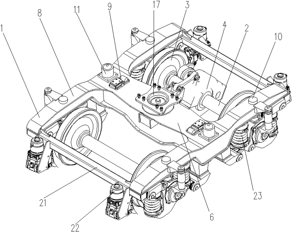
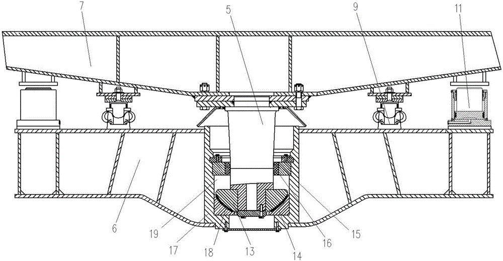
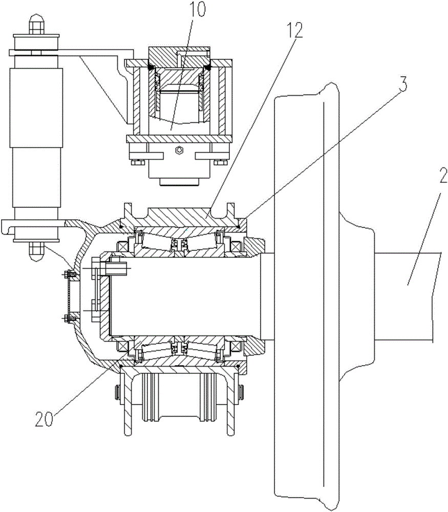
[0021] A two-axle bogie with locking function has a frame 1 with an axle 2 mounted on the frame 1 and a wheel-to-axle box 3 at both ends of the axle 2, and a driving device 4 is mounted on the axle 2 at one end of the frame 1, The center of the beam 6 of the frame 1 is provided with a center ball pin traction device, and the center ball pin traction device is fixedly connected to the frame 7 located above the frame 1, and the frame 1 is provided with constants located on both sides of the center ball pin traction device. The contact elastic friction side bearing 9 and the constant contact elastic friction side bearing 9 are supported at the bottom of the frame 7 and cooperate with the center ball pin traction device to support the frame 7 above the frame 1, and the side beam 8 of the frame 1 is provided There is a locking device that forms a rigid support between the frame 1 and the frame 7, and between the frame 1 and the wheelset axle box 3. Specifically, the locking device includes a primary locking cylinder 10 and a secondary locking cylinder 11. A series locking cylinder 10 is provided above the axle box 12 in the wheelset axle box 3 and a series locking cylinder 10 is fixed to the end of the side beam 8. The piston of the series locking cylinder 10 is supported downward on the axle box 12 to form a frame 1 and the rigid support of the axle box 12, the secondary locking cylinder 11 is fixed to the middle of the side beam 8 and the piston of the secondary locking cylinder 11 is supported upward on the frame 7 to form a rigid support between the frame 1 and the frame 7; , The center ball pin traction device includes a center ball pin 5, an upper ball disc 13, a lower ball disc 14, a traction seat 17, a retaining ring 15 and a pin sleeve 16. The pin sleeve 16 is an inner arc structure, and the traction The seat 17 is arranged in the middle of the beam 6 and the lower ball disc 14 and the retaining ring 15 located above the lower ball disc 14 are both arranged inside the traction seat 17. The lower ball disc 14 is installed on the inner bottom surface of the traction seat 17 and the retaining ring 15 is fixed An inner cavity 19 is formed between the middle rear of the traction seat 17 and the lower ball disc 14. The retaining ring 15 is provided with a pin sleeve 16 and the pin sleeve 16 is in interference fit with the retaining ring 15. The upper end of the center ball pin 5 is The frame 7 is fixedly connected and the lower end of the central ball pin 5 passes through the pin sleeve 16 and is fixedly connected to the upper ball plate 13 located in the inner cavity 19, and the central ball pin 5 moves upward so that the upper ball plate 13 and the lower ball plate 14 are separated. The center pin traction, the center ball pin 5 moves down so that the upper ball plate 13 contacts the friction pad 18 provided on the lower ball plate 14 to form a spherical center plate traction; specifically, the axle box of the wheel set axle box 3 12 is equipped with a self-sealing tapered roller bearing 20 and the self-sealing tapered roller bearing 20 is installed at the end of the axle 2.
[0022] During the operation of the equipment on the vehicle in this structure, the hydraulic control system on the frame 7 controls the primary locking cylinder 10 and the secondary locking cylinder 11, so that after the primary locking cylinder 10 and the secondary locking cylinder 11 work, the secondary The locking cylinder 11 supports the frame 7 upwards, and a series of locking cylinders 10 supports the axle box 12 downwards, so that a rigid load is formed between the frame 7 and the frame 1, the frame 1 and the axle box 12, and the driving device 4 drives the bogie during operation. Middle and low-speed travel traction is center pin traction; when the vehicle is running on the line, the upper ball disc 13 and the lower ball disc 14 at the lower end of the center ball pin 5 contact through the friction pad 18 to form a spherical core disc traction, which is compatible with the existing high-speed trucks. The traction form is the same. The vertical force, lateral force and longitudinal force are all transmitted by the spherical center plate formed by the contact between the upper ball plate 13 and the lower ball plate 14 through the friction pad 18. The center ball pin 5 makes the frame 7 and the bogie The gapless contact between the bogie and the frame 7 restricts the front and rear, left and right movement between the bogie and the frame 7. The pin sleeve 16 of the inner arc structure does not affect the relative swing of the center ball pin 5. The constant contact elastic friction side bearing 9 inhibits the vehicle's The side bearing 9 provides a stable rotational friction torque and suppresses the snaking of the vehicle, so that the vehicle has a higher running speed; the upper end of the upper ball plate 13 and the traction seat are arranged in the inner cavity 19 There is a vertical movement gap between the retaining ring 15 in 17, when the secondary locking cylinder 11 is working, the upper ball plate 13 is lifted with the frame 7 and separated from the lower ball plate 14. At this time, the vehicle is traction by the center pin. When the vehicle travels at a low speed; when the upper ball plate 13 continues to be lifted with the frame 7 to contact the retaining ring 15, it is advantageous for the frame 1 and the frame 7 to rise and recover at the same time; a series of locking cylinders 10 are fixed on the lower cover of the side beam 8, The hydraulic lock of a series of locking cylinders 10 can be installed on the frame 1 or on the control panel of the frame 7; the end beam 21 of the frame 1 is provided with unit brakes 22 at both ends. The unit brakes 22 are controlled by the contact between the brake shoes and the tread. The wheel in the axle box 3 is used for braking when parking or driving, and has a parking function, which can be used for parking braking when the air system of the vehicle is not working; the side beam 8 is provided with a series of reducing The vibration device 23 also connects the side beam 8 with the axle box 12 in the wheel set axle box 3 through a series of vibration damping devices 23. The primary vibration damping device 23 adopts the positioning of the double tie rod axle box, and the tie rod connects the axle box 12 Connected with the side beam 8, the primary shock absorber 23 provides the lateral, vertical and longitudinal stiffness required for the operation of the bogie, ensuring that the vehicle has a high running speed and good running stability.
[0023] The above-mentioned embodiments are only preferred embodiments of the present invention and are not used to limit the scope of implementation of the present invention. Therefore, all equivalent changes made with the content of the claims of the present invention shall be included in the scope of the claims of the present invention. .

PUM

no PUM

Description & Claims & Application Information

We can also present the details of the Description, Claims and Application information to help users get a comprehensive understanding of the technical details of the patent, such as background art, summary of invention, brief description of drawings, description of embodiments, and other original content. On the other hand, users can also determine the specific scope of protection of the technology through the list of claims; as well as understand the changes in the life cycle of the technology with the presentation of the patent timeline. Login to view more.

Similar technology patents

Label system-based access method

InactiveCN109871393Aimprove accuracyrun fast
Owner:云南电网有限责任公司信息中心

Workbench for detecting shaft workpieces

PendingCN114769369AImprove stabilityprevent swinging
Owner:CHANGZHOU GIKEN PRECISION CO LTD

Program protection method and device

Owner:北京顶象技术有限公司

Desk lamp for students

InactiveCN102900992Aprevent swingingincreased physical burden
Owner:SUZHOU CUIZHI NEW TECH DEV

Thrust bearing

ActiveCN101403411AUniform bearing surfaceControl radial swing amplitude
Owner:NANJING HIGH SPEED & ACCURATE GEAR GRP

AGV with clamping and holding mechanism and butt joint method thereof

PendingCN110395079Aprevent swingingImproved driving accuracy and stopping accuracy
Owner:GUANGDONG JATEN ROBOT & AUTOMATION

Classification and recommendation of technical efficacy words

  • prevent swinging

Desk lamp for students

InactiveCN102900992Aprevent swingingincreased physical burden
Owner:SUZHOU CUIZHI NEW TECH DEV

AGV with clamping and holding mechanism and butt joint method thereof

PendingCN110395079Aprevent swingingImproved driving accuracy and stopping accuracy
Owner:GUANGDONG JATEN ROBOT & AUTOMATION

Workbench for detecting shaft workpieces

PendingCN114769369AImprove stabilityprevent swinging
Owner:CHANGZHOU GIKEN PRECISION CO LTD
Why Eureka
Try Eureka