Crossed stringing device and stringing method thereof

A technology of cross racks and wiring boards, which is applied in the direction of spatial arrangement/configuration of cables, can solve problems such as short distances, and achieve the effect of convenient wiring, effective support, and not easy to connect to each other

Inactive Publication Date: 2019-11-01
STATE GRID HEBEI ELECTRIC POWER CO LTD +1
View PDF6 Cites 0 Cited by
  • Summary
  • Abstract
  • Description
  • Claims
  • Application Information

AI Technical Summary

Problems solved by technology

[0009] The current stringing device only sets an insulating net between the two crossing wires when c...

Method used


Image

  • Crossed stringing device and stringing method thereof
  • Crossed stringing device and stringing method thereof
  • Crossed stringing device and stringing method thereof

Examples


Embodiment 1

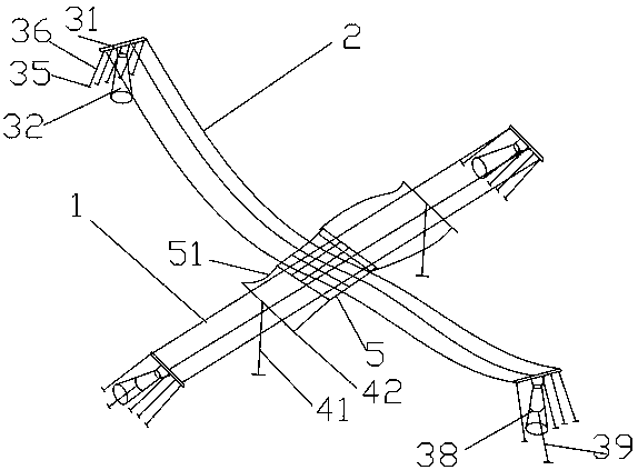
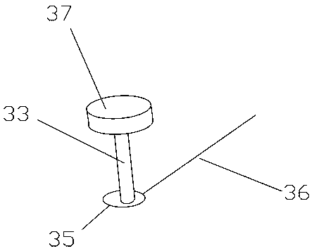
[0051] Such as figure 1 and Figure 3-6 As shown, a cross wire device includes a north-south wire 1 and an east-west wire 2, the north-south wire 1 and the east-west wire 2 are fixed on a wire rack 31, and the bottom of the wire rack 31 is provided with a tower Rod 32, the stringing plate 31 and the tower rod 32 are fixedly connected, the ground anchor is connected to the stringing plate 31, and the ground anchor is fixed on the surrounding ground, and four frames are fixed on each of the tower rods 32 Wire plate 31;

[0052] The north-south direction electric wire 1 and the east-west direction electric wire 2 are set high and low, and the high set electric wire is arranged on the support frame 41, and the described support frame 41 is respectively arranged on both sides of the low set electric wire, and the support frame 4 is set There is a support plate 42, an insulator 43 is installed on the support plate 42, and the high-set electric wire is fixed on the insulator 43;

...

Embodiment 2

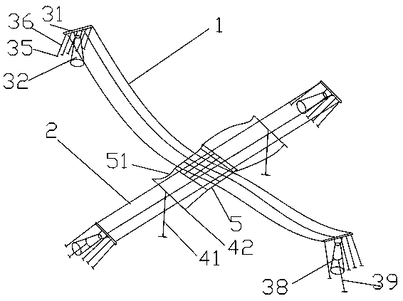
[0066] Such as Figure 2-6 As shown, a cross wire device includes a north-south wire 1 and an east-west wire 2, the north-south wire 1 and the east-west wire 2 are fixed on a wire rack 31, and the bottom of the wire rack 31 is provided with a tower Rod 32, the stringing plate 31 and the tower rod 32 are fixedly connected, the ground anchor is connected to the stringing plate 31, and the ground anchor is fixed on the surrounding ground, and four frames are fixed on each of the tower rods 32 Wire plate 31;

[0067] The north-south direction electric wire 1 and the east-west direction electric wire 2 are set high and low, and the high set electric wire is arranged on the support frame 41, and the described support frame 41 is respectively arranged on both sides of the low set electric wire, and the support frame 4 is set There is a support plate 42, an insulator 43 is installed on the support plate 42, and the high-set electric wire is fixed on the insulator 43;

[0068] Insula...


PUM

PropertyMeasurementUnit
Diameteraaaaaaaaaa

Abstract

The invention relates to a crossed stringing device. The crossed stringing device comprises a north-south direction wire and an east-west direction wire. The north-south direction wire and the east-west direction wire are arranged in a high-low mode. The high wire is arranged on a supporting frame. The supporting frame is arranged on the two sides of the low wire respectively. A supporting plate is arranged on the supporting frame. An insulator is installed on the supporting plate. The high wire is arranged fixedly on the insulator. An insulating net is arranged at the intersection of the north-south direction wire and the east-west direction wire which are arranged in the high-low mode. The insulating net is located between the high wire and the low wire. The invention further relates toa stringing method based on the crossed stringing device. The stringing method is mainly used for installing the insulating net. The crossed stringing device and the stringing method thereof are safe,effective and convenient for stringing. During the wire crossed-stringing process, wires are not easily interconnected and can be effectively supported.

Description

technical field [0001] The invention relates to the technical field of electric equipment, in particular to a cross-stringing device and a stringing method thereof. Background technique [0002] The installation process of erecting the overhead line on the erected tower with connecting fittings and insulator strings. Stringing construction is the completion stage of the transmission line construction project, and is the main process in the construction of overhead transmission lines. Its task is to erect the conductors and lightning protection lines on the erected towers according to the designed stringing stress (sag). [0003] The first preparation for laying out the ground wire is to remove the obstacles in the line corridor. It is not only to open the channel for the release of the line, but also an important condition to ensure the safe operation of the line after completion. The leveling of the construction site is also an important preparatory work for the setting-o...

Claims


Application Information

Patent Timeline
IPC IPC(8): H02G7/20
CPCH02G7/20
Inventor 刘露赵艳坤孙永辉王泽龙顾军萍李浩闪李杰
Owner STATE GRID HEBEI ELECTRIC POWER CO LTD
Why Eureka
Try Eureka