A printed circuit board testing device and a printed circuit board testing method

A printed circuit board and testing equipment technology, applied in the field of printed circuit board testing equipment, to achieve the effects of high processing efficiency, improved detection efficiency, and excellent detection efficiency

Active Publication Date: 2021-07-13
深圳市同创精密自动化设备有限公司
View PDF10 Cites 0 Cited by
  • Summary
  • Abstract
  • Description
  • Claims
  • Application Information

AI Technical Summary

Problems solved by technology

[0004] The purpose of the present invention is to solve the problems of the above-mentioned existing printed circuit board detection equipment, to provide the detection of printed circuit boards of different sizes through the clamping and moving device, and to carry out the detection of any point by adjusting the movement from left to right; Components control the detection temperature to improve the detection quality; after the detection, the product is divided into qualified area and unqualified area by distinguishing the receiving area, which is a printed circuit board inspection equipment for subsequent processing

Method used


Image

  • A printed circuit board testing device and a printed circuit board testing method
  • A printed circuit board testing device and a printed circuit board testing method
  • A printed circuit board testing device and a printed circuit board testing method

Examples


Embodiment Construction

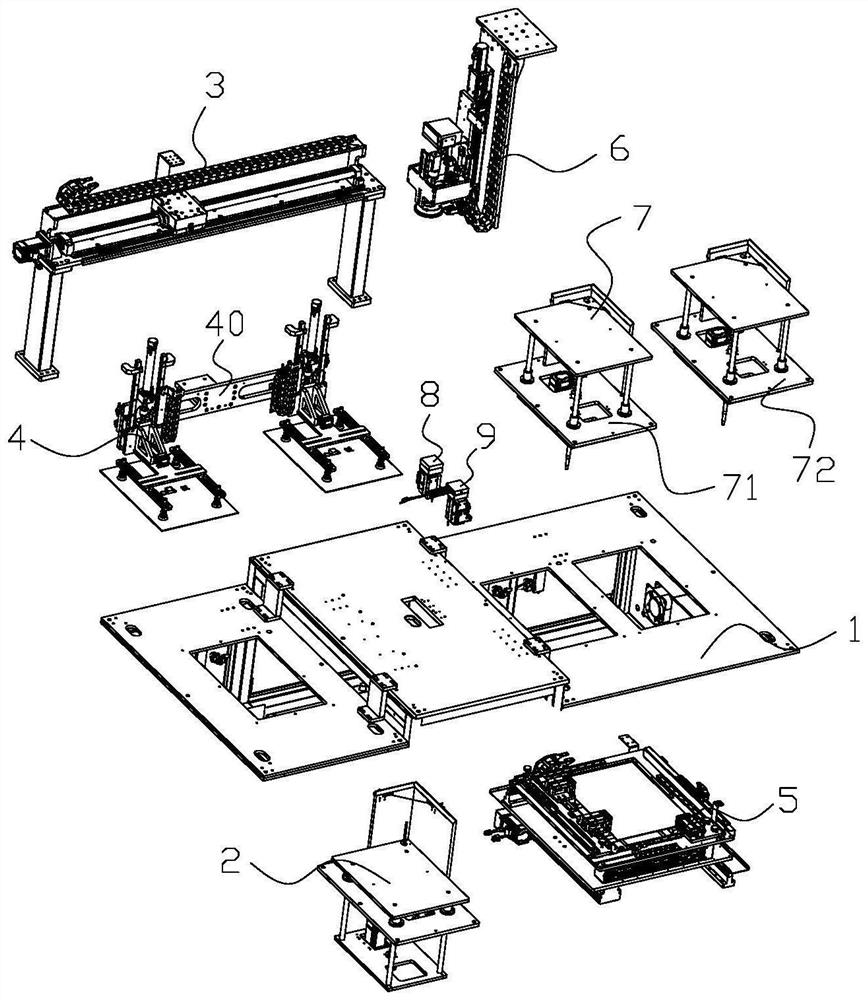
[0026] The following will clearly and completely describe the technical solutions in the embodiments of the present invention with reference to the accompanying drawings in the embodiments of the present invention. Obviously, the described embodiments are only some, not all, embodiments of the present invention.

[0027] In describing the present invention, it should be understood that the terms "upper", "lower", "front", "rear", "left", "right", "top", "bottom", "inner", " The orientation or positional relationship indicated by "outside" and so on is based on the orientation or positional relationship in the drawings, which is only for the convenience of describing the present invention and simplifying the description, rather than indicating or implying that the device or element referred to must have a specific orientation, or in a specific orientation construction, operation, and therefore should not be construed as limiting the invention.

[0028] Such as figure 1 As show...


PUM


Abstract

The invention relates to the field of processing equipment for semiconductor electronic components. A printed circuit board detection device, including a frame, a feeding device, a horizontal moving device, a retrieving device, a clamping and moving device, a detection device and a feeding device; the feeding device is used for feeding printed circuit boards; the retrieving device The device is used to clamp the printed circuit board; the clamping mobile device is used to clamp the printed circuit board and drive the printed circuit board to adjust the front, rear, left, and right; the detection device is used to detect the qualification of the printed circuit board on the clamping mobile device; The blanking device includes an unqualified blanking module and a qualified blanking module, the unqualified blanking module is used for blanking unqualified products, and the qualified blanking module is used for blanking qualified products. The technical effects of this patent are high detection versatility; multiple detection points, excellent detection efficiency, high detection quality and product differentiation after detection.

Description

technical field [0001] The invention relates to the field of processing equipment for semiconductor electronic components, in particular to a detection device and a detection method for a printed circuit board. Background technique [0002] With the rapid advancement of the degree of electronization, the application of various electronic components is becoming more and more extensive, and the printed circuit board is a commonly used electronic component, and the printed circuit board needs to be tested during the process of processing. Existing detection equipment such as the Chinese invention patent with publication number CN106824817A discloses a PCB circuit board automatic detection machine, which includes a frame and a power distribution control box, the frame is provided with a turntable connected to the turntable motor, and the turntable The detection carrier that cooperates with the product is evenly arranged on the upper surface, and the probe detection device that c...

Claims


Application Information

Patent Timeline
Patent Type & Authority Patents(China)
IPC IPC(8): B07C5/02B07C5/34B07C5/36B07C5/344
CPCB07C5/02B07C5/34B07C5/344B07C5/36
Inventor 冷梅王伟波鲁晓沈强益
Owner 深圳市同创精密自动化设备有限公司
Why Eureka
Try Eureka