
Computer-controlled supporting axle tube and blind housing welding device and using method

A technology for supporting bridge tubes and welding devices, applied in auxiliary devices, welding equipment, manufacturing tools, etc., can solve the problems of complex control, low welding quality, and poor coordination and consistency

Active Publication Date: 2019-11-05
ANYANG INST OF TECH
View PDF7 Cites 6 Cited by
  • Summary
  • Abstract
  • Description
  • Claims
  • Application Information

AI Technical Summary

Problems solved by technology

[0002] One end of the supporting bridge tube of the rear axle of the vehicle is welded to install the flange of the brake device, and the other end needs to be welded to the blind shell used to install the differential. The blind shell and the axle shell are buckled and used to install the differential. Installed on one side of the axle housing, one side of the axle housing is connected to the outer motor, and the blind housing side is not connected to the motor and is closed into a blind housing. The traditional welding of the blind housing and the supporting bridge tube adopts manual positioning and clamping of the supporting bridge tube and the blind housing. The efficiency is low, and the welding quality is not high. Even if the automatic centering clamping mechanism is adopted, the supporting bridge tube and the blind shell are centered and clamped independently, which leads to poor coordination and complicated control

Method used


Image

  • Computer-controlled supporting axle tube and blind housing welding device and using method
  • Computer-controlled supporting axle tube and blind housing welding device and using method
  • Computer-controlled supporting axle tube and blind housing welding device and using method

Examples


Embodiment Construction

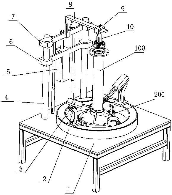
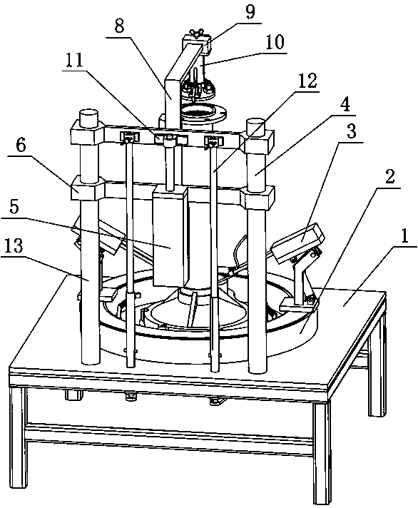
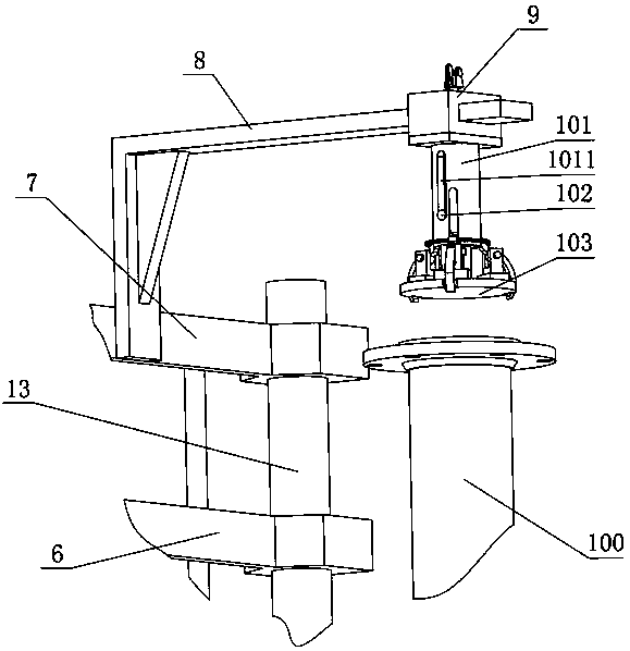
[0058] combine Figure 1-14 , a computer-controlled support bridge tube and blind shell welding device of the present invention, comprising a support plate 1, an electric turntable 2, a left welding mechanism 3, a right welding mechanism, a left support column 4, a positioning cylinder 5, and a fixed connecting plate 6. Lifting plate 7, connecting beam 8, fixed sleeve 9, support bridge tube centering mechanism 10, piston rod connecting seat 11, left blind shell pressing mechanism 12, right supporting column 13, right blind shell pressing mechanism, Blind shell positioning plate 14, computer control system, the operator is located in the position facing the support bridge tube 100, positioning cylinder 5, defines the up and down, left and right, front and rear directions of the application with the operator's up and down, left and right, front and rear directions, so that Describe this application. The support plate 1 has a left-right symmetrical structure, the left blind shel...


PUM


Abstract

The invention discloses a computer-controlled supporting axle tube and blind housing welding device. The computer-controlled supporting axle tube and blind housing welding device comprises a supporting plate, wherein the supporting plate is fixed to a left supporting column and a right supporting column, a fixing connecting plate is fixedly connected with a left supporting column and a right supporting column, a lifting plate is connected with the left supporting column and the right supporting column in a sliding manner, the fixing connecting plate is used for fixing a positioning air cylinder, a piston rod of the positioning air cylinder is fixedly connected with a lifting plate, the lifting plate is fixedly connected with a supporting axle tube centering mechanism, and is used for supporting the centering in the horizontal direction of the bridge tube and the pressing in the vertical direction; and the lifting plate is also used for fixing pressing mechanisms of a left blind housingand a right blind housing, and is used for the pressing of blind housings, a left welding mechanism and a right welding mechanism are fixed on an electric rotary table and used for supporting weldingof the supporting axle tube and the blind housings, and a blind housing positioning plate is fixed on the supporting plate and is used for positioning the blind housings and the lower end positioningof the supporting axle tube; and the positioning and clamping the supporting axle tube and the pressing the blind housings are realized through the single cylinder, and the automatic welding of the supporting axle tube and the blind housings is realized.

Description

technical field [0001] The invention relates to a computer-controlled support bridge tube and blind shell welding device and a use method, belonging to the technical field of vehicle rear axle welding equipment. Background technique [0002] One end of the supporting bridge tube of the rear axle of the vehicle is welded to install the flange of the brake device, and the other end needs to be welded to the blind shell used to install the differential. The blind shell and the axle shell are buckled and used to install the differential. Installed on one side of the axle housing, one side of the axle housing is connected to the outer motor, and the blind housing side is not connected to the motor and is closed into a blind housing. The traditional welding of the blind housing and the supporting bridge tube adopts manual positioning and clamping of the supporting bridge tube and the blind housing. The efficiency is low, and the welding quality is not high. Even if the automatic c...

Claims


Application Information

Patent Timeline
IPC IPC(8): B23K3/08B23K1/00B23K3/00
CPCB23K1/0008B23K3/00B23K3/087
Inventor 朱丽华芦娜桑书娟石玉
Owner ANYANG INST OF TECH
Learn More