
An automatic centering and clamping half-bridge welding device and welding method

An automatic centering and welding device technology, applied in welding equipment, auxiliary devices, tin feeding devices, etc., can solve the problems of easy waste products, troublesome installation and positioning process, high failure rate, etc.

Active Publication Date: 2021-04-13
ANYANG INST OF TECH
View PDF7 Cites 0 Cited by
  • Summary
  • Abstract
  • Description
  • Claims
  • Application Information

AI Technical Summary

Problems solved by technology

[0002] The rear axle is an important part of the vehicle. At present, the bridge tube and the housing of the rear axle are connected by welding. The axle housing is used to install the differential mechanism. The brake device is installed on the side of the tube away from the axle housing. The traditional axle tube and axle housing welding adopts clamping the axle housing, positioning the bridge tube, clamping the bridge tube, and then performing welding operations. The installation and positioning process of the bridge tube and the axle housing is more troublesome. , and because the axle tube, the axle housing are pressed, and the bridge tube positioning adopts an independent mechanism, the failure rate is high and waste products are prone to occur

Method used


Image

  • An automatic centering and clamping half-bridge welding device and welding method
  • An automatic centering and clamping half-bridge welding device and welding method
  • An automatic centering and clamping half-bridge welding device and welding method

Examples


Embodiment Construction

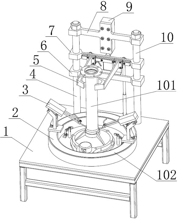
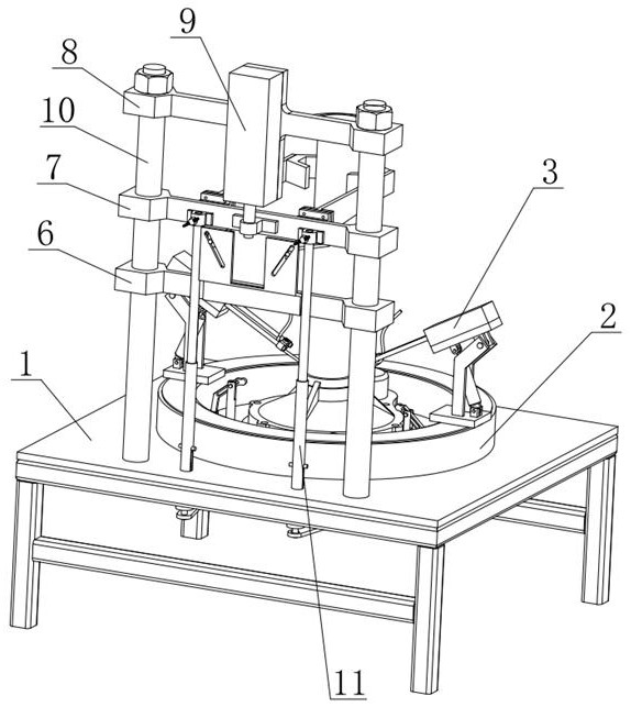
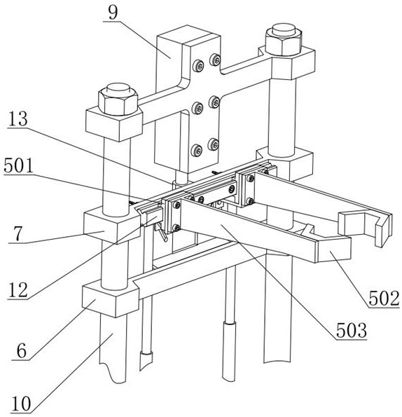
[0054] combine Figure 1-12 , an automatic centering and clamping half-bridge welding device of the present invention includes a base plate 1, an electric turntable 2, a left welding mechanism 3, a right welding mechanism, a left column 4, a left centering and pressing mechanism 5, Right centering pressing mechanism, lower fixing plate 6, sliding plate 7, upper fixing plate 8, lower pressure cylinder 9, right column 10, left axle housing pressing mechanism 11, right axle housing pressing mechanism, guide rail 12 , connecting seat 13, guide plate 14, axle housing positioning plate 15, control system, with the operator being located in the position facing the bridge tube 101 and the down-press cylinder 9, defining the application with the operator's up and down, left and right, front and rear directions Up and down, left and right, front and rear directions, in order to describe the application. The base plate 1 has a left-right symmetrical structure, the left axle housing pres...


PUM


Abstract

The invention discloses an automatic centering and clamping half-bridge welding device, which includes a base plate, left and right welding mechanisms symmetrical to the left and right sides of the base plate, left and right centering and pressing mechanisms, and left and right axle housings. The pressing mechanism, the base plate fixes the lower ends of the left and right columns, the lower fixing plate and the upper fixing plate respectively fix the upper ends of the left and right columns, the sliding plate is slidingly connected with the left and right columns, the sliding plate fixes the piston rod of the pressing cylinder, The lower pressure cylinder is fixed on the upper fixing plate, and the left and right centering and pressing mechanisms are fixed on the sliding plate to center and clamp the bridge tube at the same time. The sliding plate is elastically connected to the left and right axle housing pressing mechanisms, It is used to compress the axle housing, the electric turntable is fixed on the base plate, and the left and right welding mechanisms are fixed on the electric turntable, which is used for welding the bridge tube and the axle housing. The simultaneous clamping of the axle tube and the axle housing as well as the positioning of the axle tube are realized by the down-pressing cylinder, and the welding machine mechanism realizes the automatic welding of the axle tube and the axle housing in the circumferential direction, which is convenient for popularization and use.

Description

technical field [0001] The invention relates to an automatic centering and clamping half-bridge welding device and a welding method, in particular to a welding device and a welding method for an automatic centering and clamping half-bridge axle housing and a bridge tube. Background technique [0002] The rear axle is an important part of the vehicle. At present, the bridge tube and the housing of the rear axle are connected by welding. The axle housing is used to install the differential mechanism, which is connected to the rotating shaft of the wheel. The brake device is installed on the side of the tube away from the axle housing. The traditional axle tube and axle housing welding adopts clamping the axle housing, positioning the bridge tube, clamping the bridge tube, and then performing welding operations. The installation and positioning process of the bridge tube and the axle housing is more troublesome. , and because the axle tube, the axle housing are pressed, and the...

Claims


Application Information

Patent Timeline
Patent Type & Authority Patents(China)
IPC IPC(8): B23K1/00B23K3/06B23K3/08
CPCB23K1/0008B23K3/063B23K3/087
Inventor 翟雁郭晓波李源吴贵军国秀丽
Owner ANYANG INST OF TECH
Learn More