An eddy current resistance welding device and welding method for foil miniature parts

A technology of miniature parts and resistance welding, applied in resistance welding equipment, high-frequency current welding equipment, welding equipment, etc., can solve the problems of insufficient heat, unfused lap welding heads, etc., to achieve high production efficiency, low heat dissipation, easy to use effect achieved

Inactive Publication Date: 2020-12-18
WUHAN UNIV
View PDF7 Cites 0 Cited by
  • Summary
  • Abstract
  • Description
  • Claims
  • Application Information

AI Technical Summary

Problems solved by technology

[0005] The purpose of the present invention is to provide an eddy current resistance welding device and welding method for foil miniature parts, which solves the problem that the overlapping welding head is not fused due to insufficient heat when welding miniature foil parts with a thickness of 50um or less

Method used


Image

  • An eddy current resistance welding device and welding method for foil miniature parts
  • An eddy current resistance welding device and welding method for foil miniature parts
  • An eddy current resistance welding device and welding method for foil miniature parts

Examples


Embodiment Construction

[0032] The present invention is illustrated below in conjunction with the accompanying drawings.

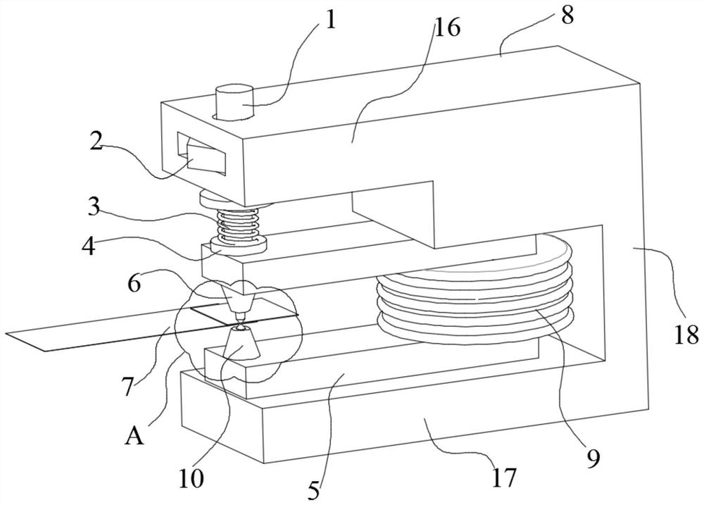
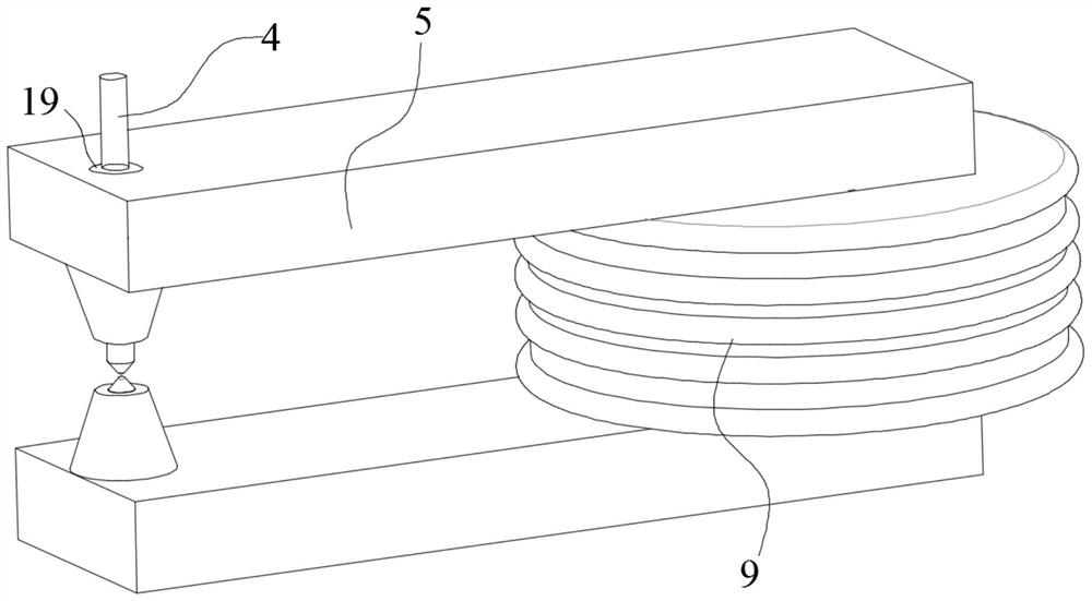
[0033] Such as Figure 1 to Figure 6 As shown, an eddy current resistance welding device for foil miniature parts includes a frame 8, a U-shaped magnetic core 5, an alternating magnetic field generator, an upper electrode 6 and a lower electrode 10; the frame 8 is U-shaped Frame 8 comprises frame upper limbs 16, frame lower limbs 17 and the vertical support 18 that upper and lower limbs are fixed.

[0034] The alternating magnetic field generating device is installed at the rear of the U-shaped magnetic core 5 for providing an alternating magnetic field for the U-shaped magnetic core 5;

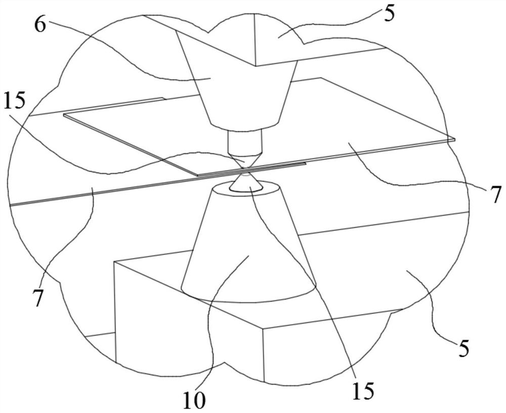
[0035] The upper electrode 6 and the lower electrode 10 are oppositely installed on the inside of the front ends of the two limbs of the U-shaped magnetic core 5, and are used to clamp the soldered foil miniature parts 7;

[0036] The upper electrode 6 and the lower electrode 10 are made of in...


PUM


Abstract

The invention discloses a vortex electric resistance welding device for foil micro-pieces and a welding method thereof. The vortex electric resistance welding device comprises a U-shaped magnetic core, an alternating magnetic field generating device, an upper electrode and a lower electrode, wherein the alternating magnetic field generating device is arranged on the rear portion of the U-shaped magnetic core and is used for providing alternating magnetic fields for the U-shaped magnetic core, the upper electrode and the lower electrode are oppositely arranged on the inner sides of the front ends of two limbs of the U-shaped magnetic core and are used for clamping to-be-welded foil micro-pieces, the upper electrode and the lower electrode are made of insulating magnetizers, and the U-shapedmagnetic core is used for conducting the alternating magnetic fields into the upper electrode and the lower electrode. According to the device, after the surfaces of the to-be-welded foil micro-pieces are cleaned up, the to-be-welded foil micro-pieces overlap each other in an up and down mode and are laid between the upper electrode and the lower electrode; a high-frequency oscillating circuit isstarted, the alternating magnetic fields are generated by the high-frequency oscillating circuit and are intensively gathered at the electrodes; and high-intensity vortexes are generated on the foilsin areas which are covered by the electrodes to heat work pieces, so that welding is completed under the electrode pressure. The device is suitable for ultra-thin work pieces, low in welding cost, easy to operate, easy to implement and high in production efficiency.

Description

technical field [0001] The invention belongs to the field of welding technology, and in particular relates to an eddy current resistance welding device and a welding method for foil miniature parts. Especially for the improvement of the method of welding different foils together in foil micro-parts with a thickness of 50um and below. Background technique [0002] As we all know, the spot welding temperature field is the comprehensive result of the interaction between heat analysis and heat dissipation; for spot welding of micro parts, less heat analysis and strong heat release are the main characteristics. In the welding process of foil miniature parts, the resistance lap welding method with low welding cost, simple operation and high production efficiency is often used; a spot welder is used to press the lap welding joint of the foil micro parts tightly between the two electrodes of the welding machine, and the resistance heat is used to The foil metal is heated to form so...

Claims


Application Information

Patent Timeline
Patent Type & Authority Patents(China)
IPC IPC(8): B23K13/01B23K11/11
CPCB23K11/11B23K11/115B23K13/01B23K13/015
Inventor 朱援祥郭嘉琳
Owner WUHAN UNIV
Why Eureka
Try Eureka