
Efficient welding method for spliced thick plates

A welding method and high-efficiency technology, applied in welding equipment, laser welding equipment, metal processing equipment, etc., can solve problems such as inability to obtain effective monitoring, reducing welding efficiency and quality, affecting the quality of thick plate workpieces, and avoiding sidewalls. Poor fusion, simplifying the welding process, reducing the effect of welding defects

Active Publication Date: 2021-06-11
广西建工集团第一安装工程有限公司
View PDF27 Cites 0 Cited by
  • Summary
  • Abstract
  • Description
  • Claims
  • Application Information

AI Technical Summary

Problems solved by technology

When argon or helium is used as the shielding gas, it is called molten inert gas shielded arc welding (called MIG); when a mixture of inert gas and oxidizing gas (oxygen and carbon dioxide) is used as the shielding gas, or carbon dioxide gas or When the mixed gas of carbon dioxide + oxygen is the shielding gas, it is collectively referred to as melting electrode active gas shielded arc welding (called MAG welding internationally). The position of the gap is often unable to be effectively monitored during the welding process, and the gap and angle are affected by factors such as material, shrinkage deformation, etc., resulting in unnecessary deviations during the arc welding process, which affects the quality of the narrow gap workpiece of the thick plate. And the welding seam is poorly formed, which reduces the welding efficiency and quality

Method used


Image

  • Efficient welding method for spliced thick plates
  • Efficient welding method for spliced thick plates
  • Efficient welding method for spliced thick plates

Examples


Embodiment Construction

[0024] In order to make the object, technical solution and advantages of the present invention clearer, the present invention will be described in further detail below with reference to the accompanying drawings and preferred embodiments. However, it should be noted that many of the details listed in the specification are only for readers to have a thorough understanding of one or more aspects of the present invention, and these aspects of the present invention can be implemented even without these specific details.

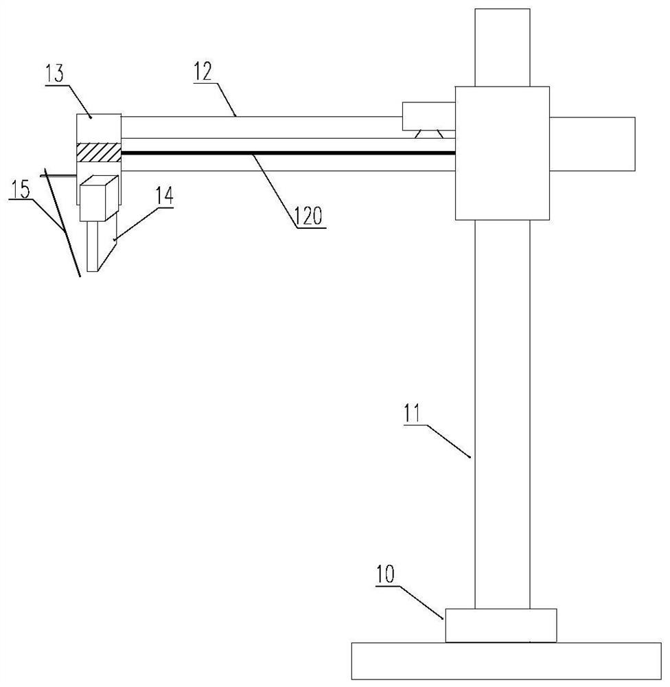
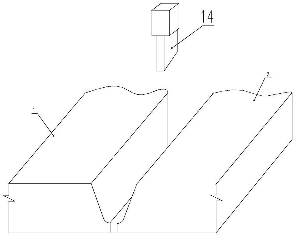
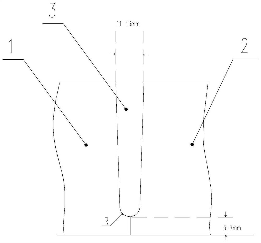
[0025] combine figure 1 , figure 2 , image 3 with Figure 4 As shown, according to an efficient welding method for spliced ​​thick plates of the present invention, a narrow gap welding device is used to weld the first spliced ​​thick plate 1 and the second spliced ​​thick plate 2, and the narrow gap welding device includes a turntable 10, a longitudinal support Frame 11, transverse swing arm 12 and narrow gap welding torch adjustment carriage 13; the vertica...


PUM


Abstract

The invention discloses an efficient welding method for spliced thick plates. The method comprises the following steps that a section of mutually symmetrical single-side groove towards the opposite sides is formed at one side or two sides of a first spliced thick plate and a second spliced thick plate, so that a U-shaped or I-shaped groove gap is formed between the spliced single-side groove of the first spliced thick plate and the spliced single-side groove of the second spliced thick plate; the first spliced thick plate and the second spliced thick plate are fixed to a welding tool clamp, and the U-shaped or I-shaped groove gap of the first spliced thick plate and the second spliced thick plate to be spliced is corrected; laser beams emitted by a laser tracking welding gun are used for conducting scanning bottoming welding on the groove bottom of the U-shaped or I-shaped groove gap, and a narrow gap welding gun is used for conducting single-layer first-pass welding on the front faces of the first spliced thick plate and the second spliced thick plate along the U-shaped or I-shaped groove gap; and then the first spliced thick plate and the second spliced thick plate are turned over and fixed for second-pass welding. According to the method, the welding process is greatly simplified, the use of welding materials is reduced, and the welding efficiency is improved.

Description

technical field [0001] The invention relates to the technical field of steel plate splicing and welding, in particular to a high-efficiency welding method for splicing thick plates. Background technique [0002] In modern welding technology, quality, efficiency, and low cost are important indicators in welding industrial production. With the rapid development of industrial equipment, construction steel structures, and national defense equipment to large capacity, high parameters, and large-scale Plate and ultra-thick plate welded structures (≥30mm) are more and more widely used, and higher requirements are put forward for the deformation and mechanical properties of welded joints of thick plates. Rigidity and restraint are large, welding residual stress and residual deformation are large, welding engineering volume is large, welding production cost is high, and the contradiction between manufacturing quality, production cycle and manufacturing cost and economic benefits of e...

Claims


Application Information

Patent Timeline
IPC IPC(8): B23K26/21B23K26/044B23K26/14B23K26/70
CPCB23K26/21B23K26/044B23K26/14B23K26/702
Inventor 韦振宇李利元黄孙民何小洪蓝克盈张琳韦明劭陆锡都
Owner 广西建工集团第一安装工程有限公司
Learn More