

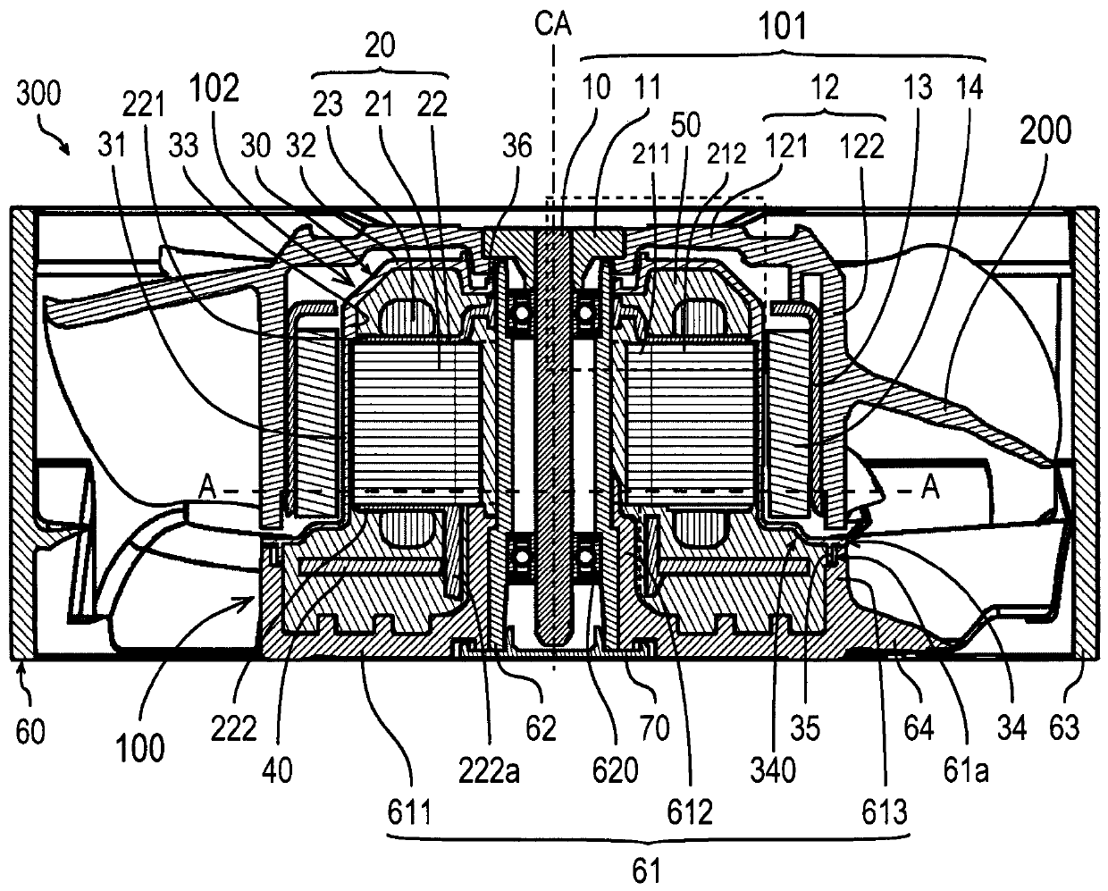
Stator unit, motor, and blower apparatus
A stator unit and stator technology, applied in the field of motors, air supply devices, and stator units, can solve problems such as the influence of rotor rotation characteristics
- Summary
- Abstract
- Description
- Claims
- Application Information
AI Technical Summary
Problems solved by technology
Method used
Image

Examples
Embodiment Construction
[0023] Hereinafter, exemplary embodiments of the present invention will be described with reference to the drawings.
[0024] In addition, in this specification, the direction parallel to central axis CA in the air blower 300 is called "axial direction." A direction from a cover 70 described later to one axial side of a shaft holder 11 described later in the axial direction is referred to as "axially upward". The direction from the shaft holder 11 to the other side in the axial direction of the cover 70 in the axial direction is referred to as "axially downward". In each constituent element, the axially upper end is referred to as an "axially upper end", and the axial position of the axially upper end is referred to as an "axially upper end". Furthermore, the axially lower end is referred to as an "axially lower end", and the axial position of the axially lower end is referred to as an "axially lower end". Furthermore, among the surfaces of the respective constituent element...
PUM
 Abstract
Description
Claims
Application Information