
Rod line head aligning device

A head-to-head and wire-to-head technology, which is applied in the field of rod-to-wire head-to-head devices, can solve problems such as increasing the load of the oil cylinder, increasing the friction between the baffle plate and the chute, and increasing production costs, so as to achieve the effect of reducing failures and weakening the degree of influence

Inactive Publication Date: 2019-11-08
PANGANG GRP ENG TECH
View PDF6 Cites 0 Cited by
  • Summary
  • Abstract
  • Description
  • Claims
  • Application Information

AI Technical Summary

Problems solved by technology

[0003] At present, the head-to-head devices used in most factories are mainly composed of hydraulic cylinders, baffles and chutes, and the left and right hydraulic cylinders are driven by the synchronous belt to drive the movement of the baffles. Frequently, after long-term work, the power of the hydraulic cylinders at both ends is different, and the baffle is prone to uneven force, and once the baffle is skewed due to uneven force, the gap between the baffle and the chute will become smaller. Unstable, if the gap is too large, the movement of the baffle will be tilted and the load on the cylinder will be increased. If the gap is too small, the friction between the baffle and the chute will increase, which will also increase the load of the cylinder, which will easily cause the cylinder of the hydraulic cylinder to hold pressure
If the above problems are found during maintenance, it is necessary to weld the chute, and then grind to ensure the gap between the chute and the baffle, which will undoubtedly increase the production cost; , the chute is easy to accumulate dust, which may cause blocking of the baffle or oil leakage of the hydraulic cylinder

Method used


Image

  • Rod line head aligning device

Examples


Embodiment Construction

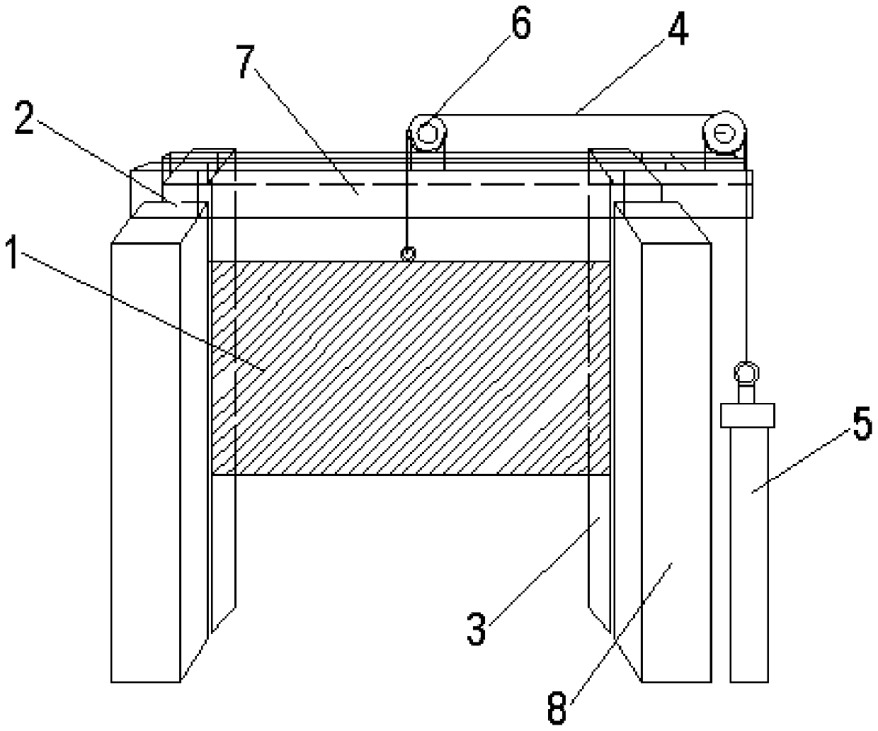
[0015] In order to facilitate understanding of the present invention, the present invention will be further described below in conjunction with the accompanying drawings.

[0016] Such as figure 1 As shown, the bar and wire aligning device of the present invention includes a mounting base 2 and a liftable aligning plate 1, a backstop 3 is provided behind the aligning plate 1, and the aligning plate 1 and the tailgate 3 are matched to each other. The rods and wires are aligned, and the back baffle 3 is also used as a load-bearing part when the rods and wires are impacted. The stopper 3 prevents it from retreating under force, and the rods and wires are braked by the plane of the trimming board 1 to achieve the purpose of trimming. After the trimming is completed, the trimming board 1 is raised, and the rods and wires are bundled and passed through to enter the follow-up work.

[0017] In the present invention, the lift of the head-to-head board 1 is realized through the joint ...


PUM


Abstract

The invention discloses a rod line head aligning device which comprises a head aligning plate and a mounting seat, wherein the head aligning plate is arranged on the mounting seat in a lifting mode, and the mounting seat comprises a rear blocking piece located behind the head aligning plate. According to the invention, a guide wire is driven by a cylinder to lift the head aligning plate, the rearblocking piece is utilized to perform limiting and blocking on the head aligning plate, the head aligning effect of the head aligning plate on the rod line is only limited by the rear blocking piece,the lifting work of the guide wire on the head aligning plate cannot influence the head aligning of the head aligning plate on the rod line, even if the lifting motion of the head aligning plate goeswrong, the head aligning work of the rod line can be normally performed due to the effect of the rear blocking piece, and the normal production can be effectively ensured; and in addition, the fallingpower of the head aligning plate can be provided by the gravity of the head aligning plate, so that the influence degree of the cylinder on the movement of the head aligning plate is weakened, and the occurrence of faults can be effectively reduced.

Description

technical field [0001] The invention relates to the technical field of steel rolling machinery and equipment, in particular to a bar-wire aligning device. Background technique [0002] Rods and wires are steel products, which are conventional products in steel rolling production. Generally, rods and wires are bundled with a baler and placed. Before and after bundling, they need to be aligned to make both ends of the rods and wires bundled. After the head-to-head operation is completed, the head-to-head device gives way, and the rods and wires are sent to the subsequent process. [0003] At present, the head-to-head devices used in most factories use hydraulic cylinders, baffles and chutes as the main components, and the left and right hydraulic cylinders are driven by the synchronous belt to move the baffle. Frequently, after long-term work, the power of the hydraulic cylinders at both ends is different, and the baffle is prone to uneven force, and once the baffle is skewed...

Claims


Application Information

Patent Timeline
IPC IPC(8): B65B63/00B65B61/24B65B27/10
CPCB65B27/10B65B61/24B65B63/00
Inventor 张合荣王跃峰漆黎明刘林李玲李军刘其鸣
Owner PANGANG GRP ENG TECH
Learn More