[0021] The following will clearly and completely describe the technical solutions in the embodiments of the present invention with reference to the accompanying drawings in the embodiments of the present invention. Obviously, the described embodiments are only some, not all, embodiments of the present invention. Based on the embodiments of the present invention, all other embodiments obtained by persons of ordinary skill in the art without making creative efforts belong to the protection scope of the present invention.
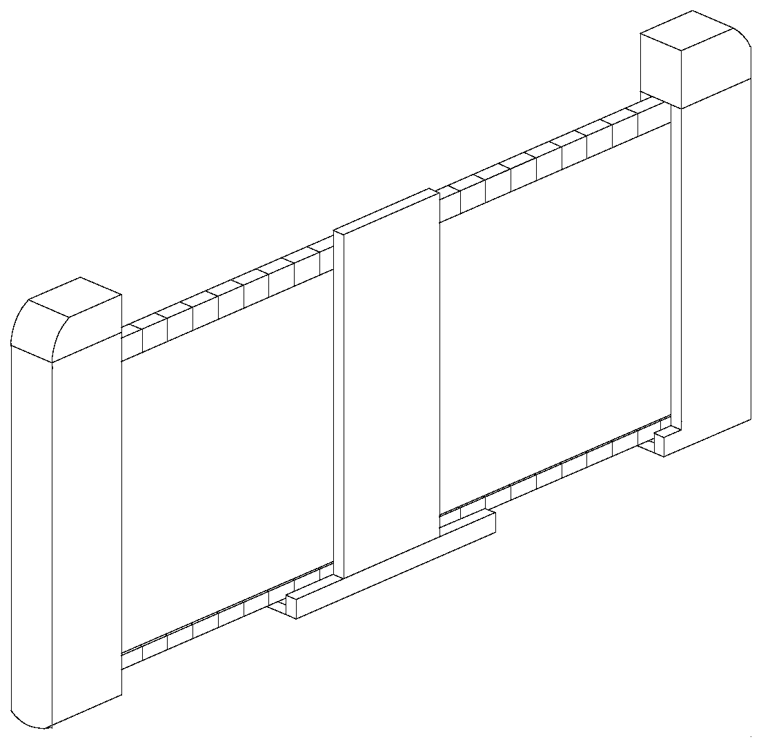
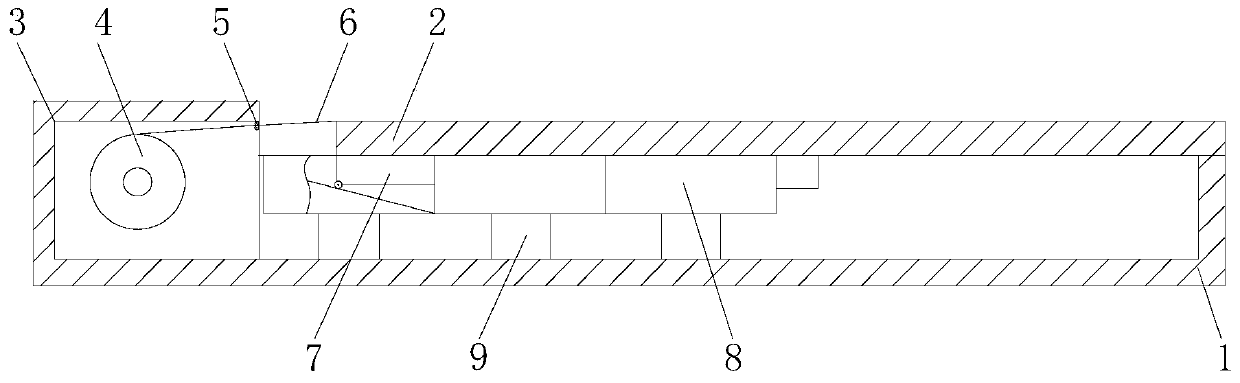
[0022] see Figure 2-7 , a pull-out flexible screen, including a housing 1 and a support plate 2, the housing 1 and the support plate 2 are slidably connected, one side of the housing 1 is provided with a rewinding chamber 3, and a rewinding chamber 3 is installed in the rewinding chamber 3 Roller 4, the winding roller 4 has a self-rolling function, the winding roller 4 rolls up the flexible screen 6, the outer wall of the winding roller 4 is provided with a flexible screen 6, one side of the flexible screen 6 is fixedly connected to the support plate 2, and the support plate The flexible screen 6 connected to the 2 is the main operating area between the support plate 2 and the winding roller 4 to assist display and auxiliary operation. An adjustable protective roller 5 is provided between the support plate 2 and the winding roller 4. The adjustable protection roller 5 is two close rollers, the highest point of the lowered roller body is flush with the upper surface of the support plate 2, so as to avoid collision between the support plate 2 and the shell 1, and the gap between the support plate 2 and the shell 1 There are movable support blocks 8, the number and size of the movable support blocks 8 are appropriate, and after the support plate 2 moves away, the movable support blocks 8 pop up to fill the position of the support plate 2 to support the flexible screen 6, and multiple movable support blocks 8 can be more flexible. Flexible adjustment of the total size of the screen, the movable support block 8 and the support plate 2 are slidingly connected by the extrusion bar 7, the extrusion bar 7 presses the movable support block 8, and as the extrusion bar 7 slides away, the movable support block 8 pops up to fill The support plate 2 leaves the gap generated, and the lower end of the movable support block 8 is fixedly connected with the housing 1 through the elastic member 9. In this embodiment, the elastic member 9 adopts a return spring, and the movable support block 8 is filled and supported by the elastic force of the elastic member 9. Plate 2 leaves the resulting gap.
[0023] As an embodiment of the present invention, inclined surfaces 10 are provided on both sides of the movable support block 8, and the extruded bar 7 slides on the inclined surfaces 10, so that the movable support block 8 bounces up gradually under the elastic force of the elastic member 9 to avoid The excessive elastic force produces big impact force, and the two ends of movable support block 8 are provided with limit block 11, and movable support block 8 blocks the inner wall of housing 1 by limit block 11, and movable support block 8 is limited in height, makes movable The upper end surface of the support block 8 just fits the flexible screen 6 and does not generate a large force on the flexible screen 6. The height of the inclined surface 10 is the same as the distance from the movable support block 8 to the flexible screen 6. When the extrusion bar 7 and the movable support block 8 When out of contact, the movable support block 8 just reaches the highest position, the inclined surface 10 is slidingly connected with the extruding bar 7, a pulley is installed at the lower end of the extruding bar 7, the inclined surface 10 is aligned with the chute 12, and the extruding bar 7 is completely and movable support When the block 8 is out of contact, the extruded bar 7 slides into the chute 12, and the interaction between the inclined surface 10 and the extruded bar 7 also plays the role of locking the position of the supporting plate 2.
[0024] As an embodiment of the present invention, protective covers 13 are provided on both sides of the flexible screen 6, and the protective covers 13 erect the flexible screen 6 so that when the flexible screen 6 is rolled up on the winding roller 4, the No force will be generated between the flexible screens 6, reducing the wear of the flexible screen 6. At the same time, the traction force is mainly realized through the protective cover 13 to further reduce the force on the force. The protective cover 13 is slidably connected with the movable support block 8, and the movable The support block 8 is provided with a positioning groove 14 corresponding to the protective cover 13 , and the protective cover 13 is accommodated by the positioning groove 14 , so that the upper surface of the movable support block 8 is attached to the flexible screen 6 .
[0025] As an embodiment of the present invention, the adjustable protection roller 5 includes a control block 51, an adjustment wedge 52, an adjustment block 53, a movable frame 54, a protection roller body 55 and a fixed frame 56, and the fixed frame 56 is fixedly connected to the winding cavity 3 , the fixed frame 56 and the movable frame 54 are slidingly connected, the control block 51 is fixedly connected with two protective roller bodies 55, the upper end of the protective roller body 55 is provided with an adjustment block 53, the control block 51 is movably connected with the winding chamber 3, and the control block 51 The lower end is provided with an adjustment wedge 52, and the adjustment block 53 is provided with a lifting lug adapted to the adjustment wedge 52. When the control block 51 is moved, the adjustment wedge 52 is inserted into the lug on the adjustment block 53, and the height of the adjustment block 53 rises. High, drive the movable frame 54 and the protective roller body 55 to rise, and then make the flexible screen 6 be raised, reduce the friction between the flexible screen 6 and the movable support block 8, and reduce the wear of the flexible screen 6.
[0026] Working principle of the present invention:
[0027] Toggle the control block 51 to adjust the height of the protective roller body 55, so that the end of the flexible screen 6 close to the winding roller 4 is raised, the support plate 2 is twitched, the extrusion bar 7 and the inclined surface 10 slide relative to each other, and the height of the movable support block 8 is adjusted accordingly. As the inclined surface 10 increases, it rises slowly until the limit block 11 clamps the housing 1, and the movable support block 8 is even the highest. Pull out a screen of an appropriate size as required, and the movable support block 8 rises with the sliding sequence of the support plate 2 , after stopping, the winding roller 4 automatically rolls back the excess screen, and then dials back the control block 51 to restore the protective roller body 55 to the original height, and the flexible screen 6 is attached to the movable support block 8. When pulling back, the control block 51 is moved Adjust the height of the protective roller body 55, slowly dial back the support plate 2, the interaction between the squeeze bar 7 and the inclined surface 10, and press down the movable support block 8 until all the movable support blocks 8 are pressed back to the original position, and the flexible screen 6 is rolling. Retract under the effect of roller 4, reset adjustable protection roller 5 after winding is completed.
[0028] It should be noted that in this article, relational terms such as first and second are only used to distinguish one entity or operation from another entity or operation, and do not necessarily require or imply that there is a relationship between these entities or operations. There is no such actual relationship or order between them. Furthermore, the term "comprises", "comprises" or any other variation thereof is intended to cover a non-exclusive inclusion such that a process, method, article, or apparatus comprising a set of elements includes not only those elements, but also includes elements not expressly listed. other elements of or also include elements inherent in such a process, method, article, or device.
[0029] Although the embodiments of the present invention have been shown and described, those skilled in the art can understand that various changes, modifications and substitutions can be made to these embodiments without departing from the principle and spirit of the present invention. and modifications, the scope of the invention is defined by the appended claims and their equivalents.