Workpiece loading device

A technology of pushing device and workpiece, applied in metal processing, manufacturing tools, metal processing equipment, etc., can solve problems such as influence, production obstacle, material displacement, etc.

Pending Publication Date: 2019-11-12
SUZHOU INST OF INDAL TECH
View PDF2 Cites 0 Cited by
  • Summary
  • Abstract
  • Description
  • Claims
  • Application Information

AI Technical Summary

Problems solved by technology

[0006] However, there are still the following defects: first, in this type of feeding method, the material falls on the material distribution support column in the material distribution limit gap, and there is no limit for the material distribution gap, once multiple materials fall into the material distribution limit On the material distribution support column in the gap, it will directly affect the loading and unloading of the next process
Second, a semi-enclosed storage cavity is formed through the combination of the material distribution limit gap and the material distribution support column to limit the storage of materials, but when the material distribution support column pushes the material, there is no limit structure for the material , it is easy to cause the displacement of the material, which is also easy to cause the position of the material to be inaccurate, which will affect the material of the next process, thereby causing production obstacles, affecting the efficiency of the production process, and even greatly affecting the production pass rate

Method used


Image

  • Workpiece loading device
  • Workpiece loading device
  • Workpiece loading device

Examples


Embodiment Construction

[0026] The present invention will now be further described in detail in conjunction with the accompanying drawings and embodiments. These drawings are all simplified schematic diagrams, only illustrating the basic structure of the present invention in a schematic manner, so it only shows the composition related to the present invention.

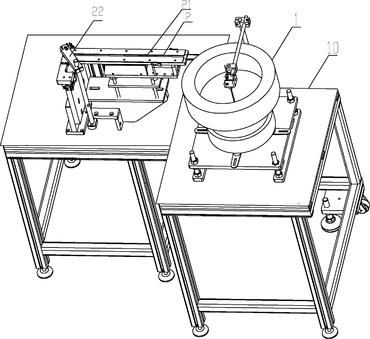
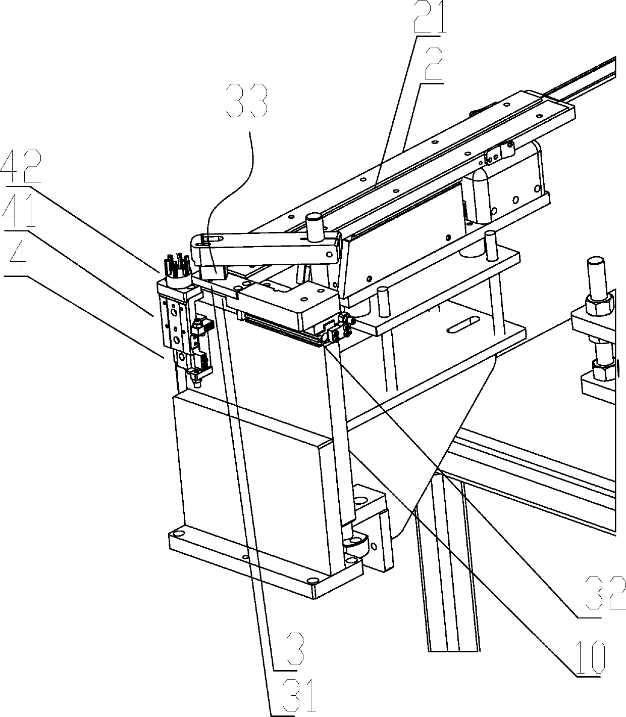
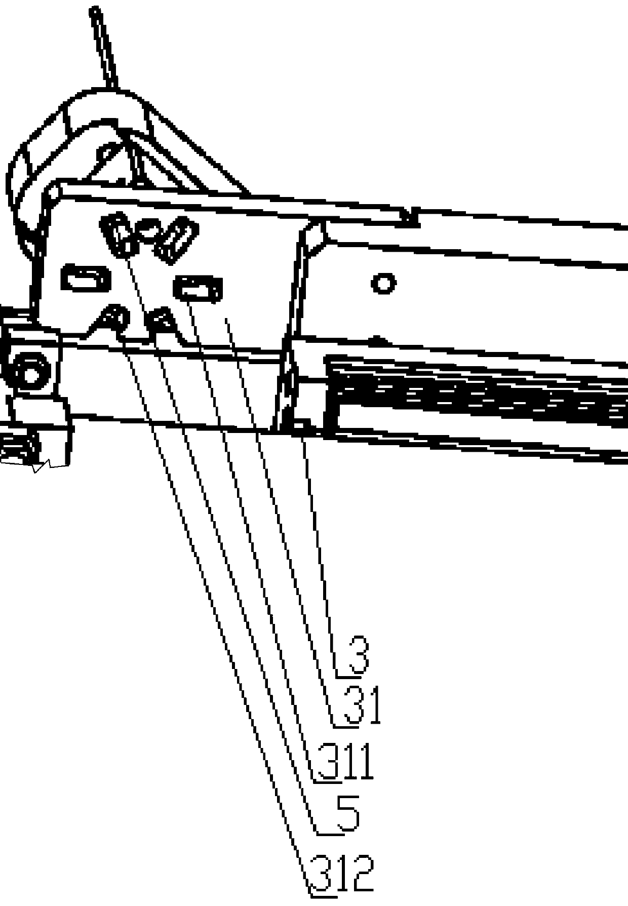
[0027] Such as Figure 1~Figure 5 As shown, this embodiment discloses a workpiece feeding device, including a vibrating plate 1 arranged on a frame 10, the discharge port on the vibrating plate 1 is connected to one end of the conveying channel 2, and the other end of the conveying material channel 2 A pushing device 4 is connected, and a pushing device 3 is arranged between the conveying channel 2 and the pushing device 4; The plate 31 and the transfer plate 31 are provided with a workpiece groove 312 when opening, and a plurality of through grooves 311 are arranged in the workpiece groove 312 . And the side of the delivery channel 2 close ...


PUM


Abstract

The invention relates to a workpiece loading device. The workpiece loading device comprises a vibration disc arranged on a rack, a discharging opening of the vibration disc is connected with one end of a conveying material way, the other end of the conveying material way is connected with a pushing device, a stirring device is arranged between the conveying material way and the pushing device, andcomprises an ejection air cylinder arranged on the rack, a transfer plate is connected to the ejection air cylinder, and a workpiece groove with an opening is formed in the transfer plate. Accordingto the workpiece loading device, conveyed materials can be subjected to batched loading, taking pre-separation operation is carried out, and limiting and gesture calibration of the material can be achieved.

Description

technical field [0001] The invention relates to the technical field of mechanical processing detection, in particular to the technical field of processing and production detection of electrical appliances, and in particular to a workpiece feeding device. Background technique [0002] In the prior art, the patent name: an automatic pressure bearing and bushing mechanism (patent number: CN201410182069.0), discloses an automatic pressure bearing and bushing mechanism, which includes a frame, a feeding line, an automatic feeding Mechanism, product automatic shift positioning mechanism, positioning mechanism, bush vibrating plate, automatic bush pressing mechanism, bearing swing plate, automatic bearing pressing mechanism, automatic unloading mechanism and unloading line, the product arrives at the designated position through the loading line, The automatic feeding mechanism clamps the product through the jaws, the rotating cylinder rotates, and the stepping motor performs a disp...

Claims


Application Information

Patent Timeline
Patent Type & Authority Applications(China)
IPC IPC(8): B23P19/00B23P19/02
CPCB23P19/001B23P19/004B23P19/007B23P19/02
Inventor 黄华栋单鑫鑫王耀孙奎奎吴凯吕天恒
Owner SUZHOU INST OF INDAL TECH
Why Eureka
Try Eureka