
Novel transformer oil level gauge structure

A technology of transformer oil and oil level gauge, which is applied in the direction of transformer/inductor cooling, buoy liquid level indicator, etc., which can solve the problems of broken float rod, bad float device, false oil level, etc., and reduce the overall size , to avoid the phenomenon of false oil level, to avoid the effect of fracture

Pending Publication Date: 2019-11-12
KERUN ELECTRIC POWER TECH CO LTD
View PDF0 Cites 0 Cited by
  • Summary
  • Abstract
  • Description
  • Claims
  • Application Information

AI Technical Summary

Problems solved by technology

[0003] Due to the strong shaking of the oil level in the transformer oil conservator caused by the bumps, shakes and vibrations of the on-site road conditions that are likely to occur during the moving process of the vehicle-mounted transformer, on the one hand, it will have a negative impact on the float device, seriously On the other hand, due to the simultaneous shaking of the oil surface and the capsule, the float will be entangled by the capsule and lose the function of the float, resulting in a false oil level.
[0004] In addition, the width and length of the existing vehicle-mounted transformers are relatively large, and the position of the oil conservator is horizontally supported at the end, which is not conducive to the realization of "miniaturization" of the product

Method used


Image

  • Novel transformer oil level gauge structure
  • Novel transformer oil level gauge structure
  • Novel transformer oil level gauge structure

Examples


Embodiment Construction

[0025] The following will clearly and completely describe the technical solutions in the embodiments of the present invention with reference to the accompanying drawings in the embodiments of the present invention. Obviously, the described embodiments are only some, not all, embodiments of the present invention. Based on the embodiments of the present invention, all other embodiments obtained by persons of ordinary skill in the art without making creative efforts belong to the protection scope of the present invention.

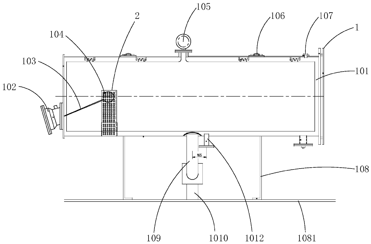
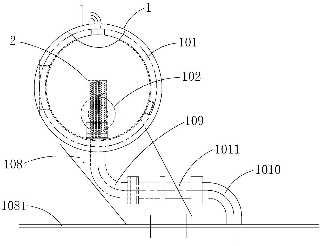
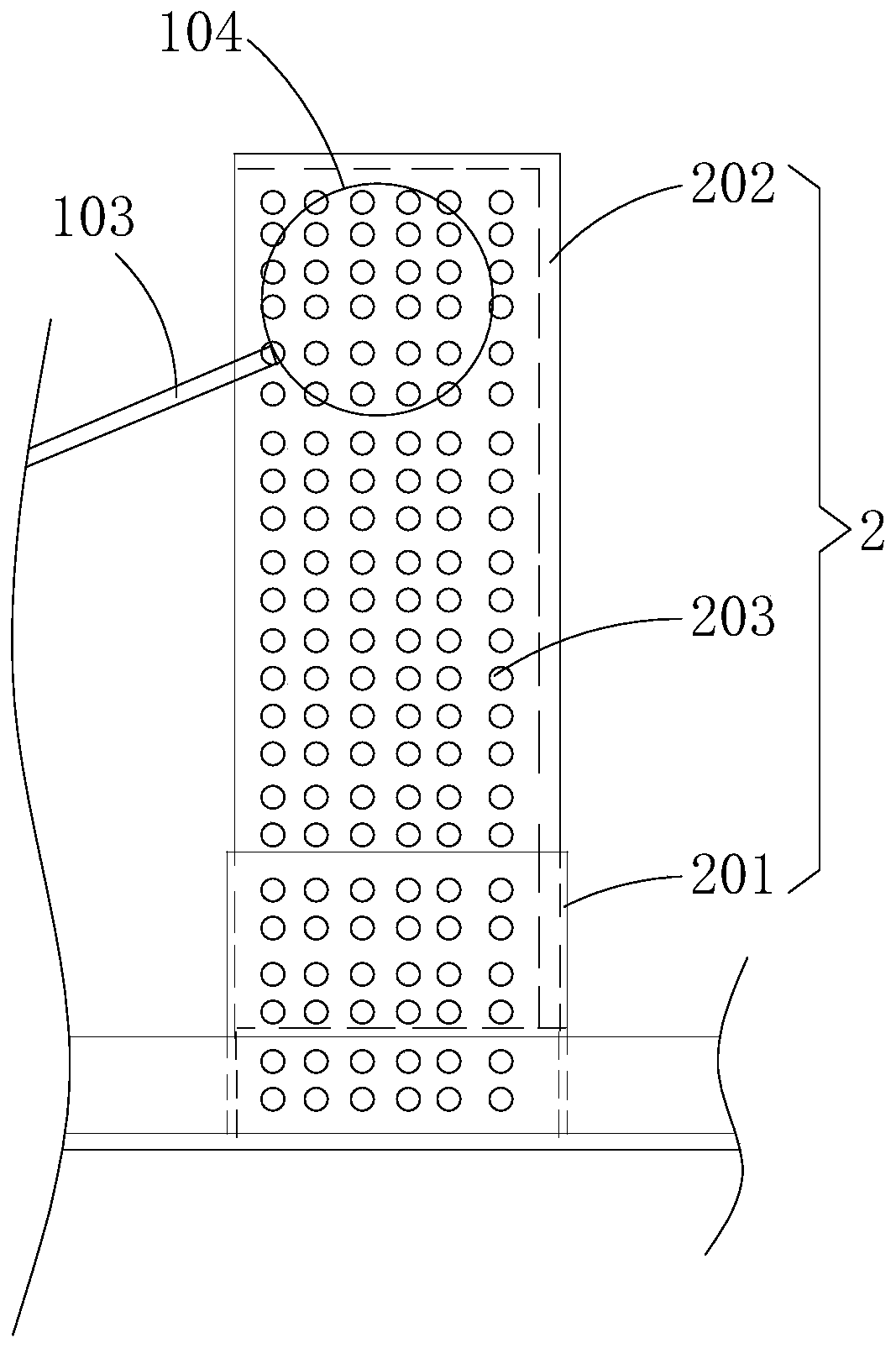
[0026] see Figure 1-4 , the present invention provides a technical solution: a novel transformer oil level gauge structure, including an oil storage mechanism 1 and an airbag replacement mechanism 2, the inner bottom surface of the oil storage mechanism 1 is connected to the bottom end of the airbag replacement mechanism 2.

[0027] The oil storage mechanism 1 is composed of an oil storage tank 101, an oil level gauge 102, a ball float rod 103, an oil level b...


PUM


Abstract

The invention discloses a novel transformer oil level gauge structure. The structure comprises an oil storage mechanism and an air bag replacing mechanism; the bottom surface of the interior of the oil storage mechanism is connected with the bottom end of the air bag replacing mechanism, and the main body of the oil storage mechanism is an oil conservator; an oil level gauge is fixedly installed at the left end of the oil conservator, the part of the oil level gauge, which is located inside the oil conservator, is connected with a ball float rod, and one end, which is far away from the oil level gauge, of the ball float rod is fixedly connected with an oil level buoy; the left side and the right side of the lower end of the oil conservator are fixedly connected with oil conservator fixingframes; and a short U type bent plate is welded to the left position of the inside bottom surface of the oil conservator, a protection buoy U type bent plate is arranged on the inner side of the shortU type bent plate, circulation holes are formed in the outer sides of the short U type bent plate and the protection buoy U type bent plate, and the short U type bent plate and the protection buoy Utype bent plate are connected through bolts and nuts. The novel transformer oil level gauge structure avoids the occurrence of the phenomena of breakage and false oil level of the ball float rod, reduces the vehicle-mounted transformer and realizes the effects of product miniaturization and the like.

Description

technical field [0001] The invention relates to the technical field of transformer oil level gauges, in particular to a novel transformer oil level gauge structure. Background technique [0002] Usually, a capsule and an oil level float device are installed in the transformer oil conservator. Under normal circumstances, the float moves up and down to display the online oil level of the transformer during operation and whether it is within the safe range. [0003] Due to the strong shaking of the oil level in the transformer oil conservator caused by the bumps, shakes and vibrations of the on-site road conditions that are likely to occur during the moving process of the vehicle-mounted transformer, on the one hand, it will have a negative impact on the float device, seriously On the other hand, due to the simultaneous shaking of the oil surface and the capsule, the float will be entangled by the capsule and lose the function of the float, resulting in a false oil level. [0...

Claims


Application Information

Patent Timeline
IPC IPC(8): G01F23/32H01F27/14
CPCG01F23/32H01F27/14
Inventor 章群峰任谦葛其运董晓军姜毅琚烜
Owner KERUN ELECTRIC POWER TECH CO LTD
Learn More