Key structure

A key and key cap technology, applied in the field of mechanical key structure, can solve the problems of permanent deformation of the bracket, damage to the stability of the key cap, affecting the stability of the key structure, and achieve the effect of good trajectory stability.

Active Publication Date: 2019-11-12
DARFON ELECTRONICS (SUZHOU) CO LTD +1
View PDF10 Cites 0 Cited by
  • Summary
  • Abstract
  • Description
  • Claims
  • Application Information

AI Technical Summary

Problems solved by technology

In addition, the tooth structure only fits the concave-convex structure of the occlusal end surface area, and the end structure of the bracket has multiple orientations that are not restricted, which also damages the stability of the keycap.
[0004] Furthermore, when the overall size of the button structure is reduced, it is difficult for the bracket to have enough space to form a complete hole shaft structure; even if a complete hole shaft structure is formed, it is likely to cause insufficient structural strength and reduce the stability of the pivotal connection of the bracket
In addition, in general, the complete bore-shaft structure may cause permanent deformation or damage to the stent during assembly
When the overall size of the button structure is reduced, this permanent deformation or damage is likely to affect the strength of the bracket itself and the stability of the combination between the two, further affecting the actuation stability of the button structure

Method used


Image

  • Key structure
  • Key structure
  • Key structure

Examples


Embodiment Construction

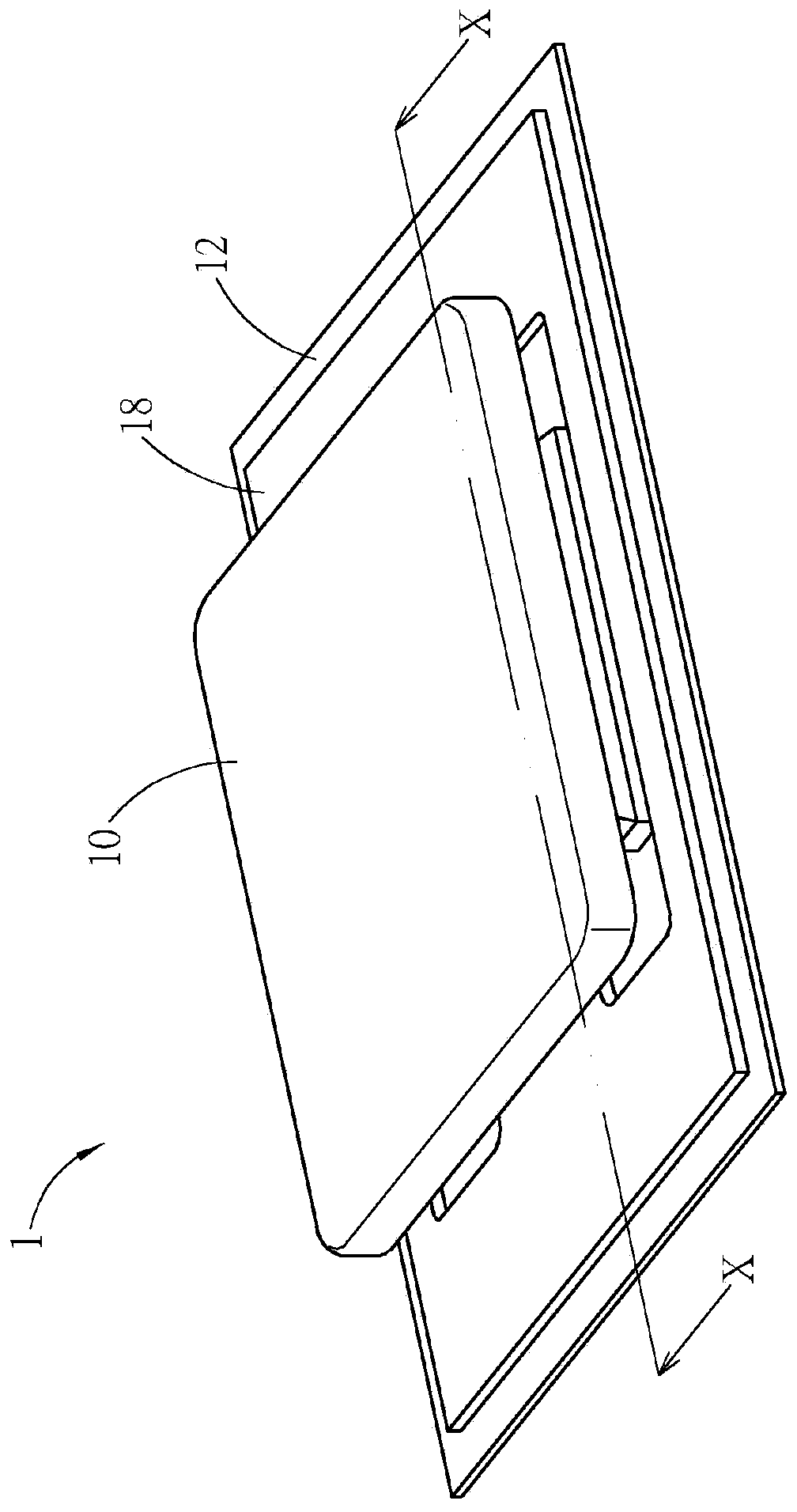
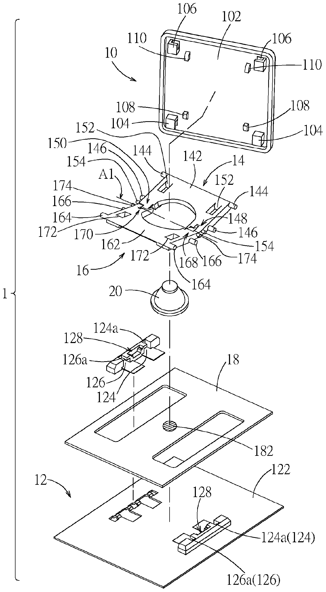
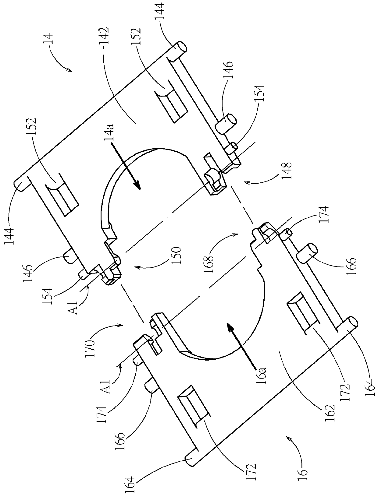
[0042] see figure 1 and figure 2 . The key structure 1 according to an embodiment includes a keycap 10 , a base 12 , a first bracket 14 , a second bracket 16 , a switch circuit board 18 and an elastic reset member 20 . The base 12 is arranged below the keycap 10, and the first bracket 14 and the second bracket 16 are relative to the rotation axis A1 (shown by a dotted line on figure 2 Middle) are pivotally connected to each other and are respectively connected between the keycap 10 and the base 12, the switch circuit board 18 is placed on the base 12, and the elastic return member 20 corresponds to the switch 182 of the switch circuit board 18 (shown in a circle with a hatched line). figure 2 Middle) placed on the switch circuit board 18. The keycap 10 can move vertically up and down relative to the base 12 through the first support 14 and the second support 16 , and the keycap 10 moving downward can press the elastic reset member 20 to trigger the switch 182 . In actua...


PUM


Abstract

The invention discloses a key structure, which comprises a key cap, a base and two brackets pivotally connected to each other with respect to the rotating axial and connected between the key cap and the base. One of the brackets includes a first shaft groove, a first shaft portion and a partition groove formed therebetween; the other bracket includes a second shaft groove, a second shaft portion and a partition wall therebetween. The two brackets are respectively rotatably disposed in the second shaft groove and the first shaft groove via the first shaft portion and the second shaft portion tobe pivotally connected with respect to the rotating axis; the partition wall is inserted into the partition groove; and the key cap can move up and down relative to the base via the two brackets. Thekey structure of the invention adopts a non-complete hole axis structure, so that the structural strength of the bracket itself can be maintained. Moreover, each of the brackets has a shaft portion and a shaft groove structure, and by fitting each other, a certain degree of pivot strength and rotational stability can be maintained.

Description

technical field [0001] The invention relates to a mechanical key structure, in particular to a mechanical key structure whose key cap is supported and actuated by two brackets. Background technique [0002] Many mechanical key structures use a scissors bracket to support the keycap, and the two brackets of the scissors bracket are generally pivotally connected by a complete hole shaft structure located in the middle of the bracket. The hole-axis fit can provide good mutual pivoting stability of the brackets. However, if the brackets are pivotally connected with a complete hole shaft structure, the two brackets must be assembled along the pivot axis, or the two brackets must be assembled at a specific angle. It is difficult to avoid misalignment and overcut, which will affect yield and production capacity. [0003] U.S. Patent No. 6,060,676 discloses that the two brackets are occludedly connected by the toothed structure at the end of the arm. This type of toothed structure...

Claims


Application Information

Patent Timeline
Patent Type & Authority Applications(China)
IPC IPC(8): H01H13/705
CPCH01H13/705H01H2233/074
Inventor 赵令溪
Owner DARFON ELECTRONICS (SUZHOU) CO LTD
Why Eureka
Try Eureka