Antenna device and mobile terminal

An antenna device and mobile terminal technology, which is applied to antenna supports/installation devices, antenna coupling, independent non-interacting antenna combinations, etc., can solve the problems of deteriorating antenna performance, poor isolation of secondary antennas, and inability to discharge static electricity. Achieve the effect of solving electrostatic discharge, prolonging service life and improving appearance effect

Active Publication Date: 2016-02-03
GUANGDONG OPPO MOBILE TELECOMM CORP LTD
View PDF6 Cites 15 Cited by
  • Summary
  • Abstract
  • Description
  • Claims
  • Application Information

AI Technical Summary

Problems solved by technology

[0003] However, due to the focal length requirements of the imaging of the rear camera, it cannot be as thin as the other parts of the whole machine and is relatively protruding, which makes the structural strength of the camera poor. On the other hand, it will also affect the appearance effect. Therefore, by introducing metal However, at the same time, the introduction of metal parts will deteriorate the performance of the antenna, and it will also cause electrostatic risks in such a convex part of the camera; the antenna interface is very sensitive to electrostatic discharge, and if the protection is not good, it may cause internal radio frequency The device is permanently damaged, and the mobile phone will not be able to transmit signals through electromagnetic waves, which will eventually affect the communication quality of the system
[0004] In addition, in order to support more wireless functions, current smartphones often increase the number of mobile phone antennas, resulting in poor isolation between antennas and mutual interference between antennas, which will also affect communication quality and poor user experience.
[0005] From the above, there are technical problems in the prior art that static electricity cannot be released due to the introduction of metal parts, and the isolation between the secondary antennas is poor

Method used


Image

  • Antenna device and mobile terminal
  • Antenna device and mobile terminal
  • Antenna device and mobile terminal

Examples


Embodiment 1

[0042] An embodiment of the present invention provides an antenna device, including: an antenna bracket, a camera, a metal piece with an opening, and an earphone holder;

[0043] Multiple antennas are arranged on the antenna bracket, and the antennas are connected to corresponding antenna feed points on the main board of the mobile terminal;

[0044] The metal piece is arranged on the antenna support and is located between two adjacent antennas;

[0045] The camera is set under the metal part;

[0046] Wherein, the metal piece has a signal transmission end, and the signal transmission end is grounded.

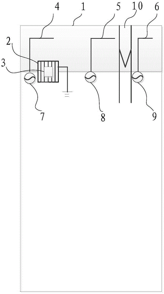
[0047] For example, if figure 1 As shown, the antenna device includes: an antenna bracket 1, a metal piece 2 with an opening, and a camera 3;

[0048] The antenna device in the embodiment of the present invention further includes: antenna 4, antenna 5, antenna 6, antenna feed point 7, feed point 8, feed point 9 and earphone socket 10;

[0049] The metal piece is arranged on...

Embodiment 2

[0064] An embodiment of the present invention provides a mobile terminal, including: an antenna bracket, a camera, an earphone holder, a main board, and a metal piece with an opening;

[0065] The main board is connected to the antenna bracket and has multiple antenna feed points;

[0066] There are multiple antennas on the antenna bracket, and the antennas are connected to the corresponding antenna feed points on the main board;

[0067] The metal piece is arranged on the antenna support and the main board, and is located between two adjacent antennas;

[0068] The camera is set under the metal part;

[0069] Wherein, the metal piece has a signal transmission end, and the signal transmission end is grounded.

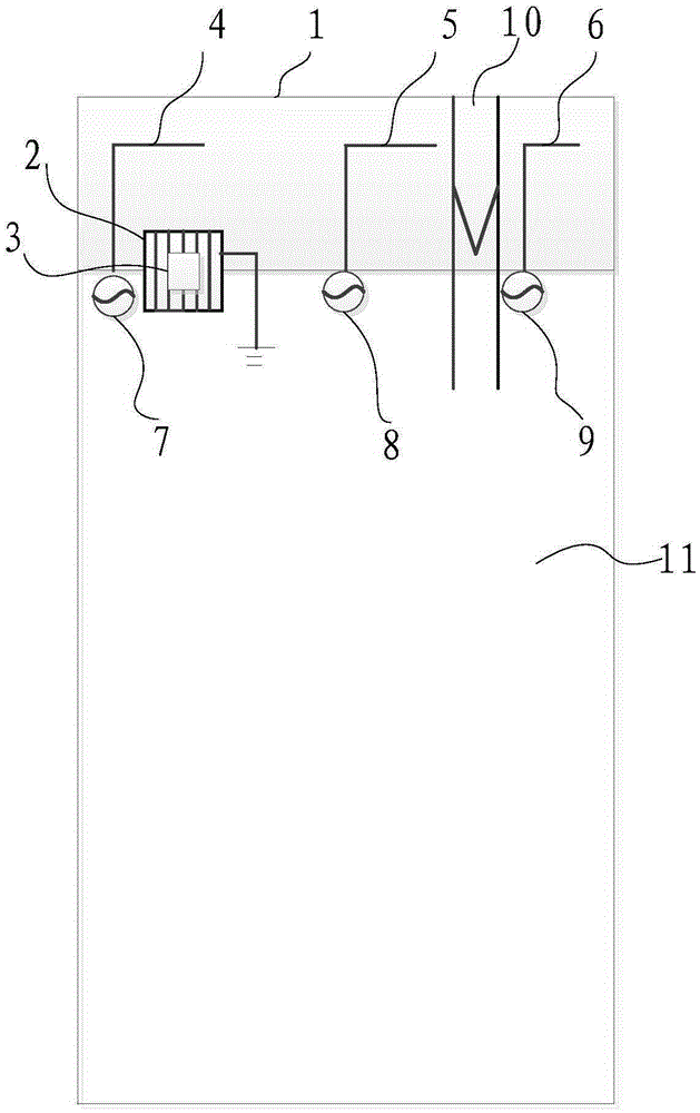
[0070] For example, if image 3 As shown, the mobile terminal in this embodiment includes: an antenna bracket 1, a metal part 2 with an opening, a camera 3, an earphone socket 10, and a main board 11;

[0071] The mobile terminal in the embodiment of the present inv...


PUM


Abstract

The embodiment of the invention discloses an antenna device and a mobile terminal. The antenna device disclosed by the embodiment of the invention comprises an antenna support, a camera and metal parts with openings, wherein a plurality of antennas are disposed on the antenna support, and the antennas are connected to corresponding antenna feed points on a mobile terminal mainboard; the metal part is disposed on the antenna support and located between the two adjacent antennas; the camera is disposed under the metal part; and the metal part is equipped with a signal transmission terminal and the signal transmission terminal is grounded. The antenna device and the mobile terminal disclosed by the embodiment of the invention are grounded by the signal transmission terminal on the metal part and can release static electricity on the device. Meanwhile, a good isolation degree is formed between two electric wires adjacent to the metal part because of the metal part grounding.

Description

technical field [0001] The present invention relates to the technical field of terminals, in particular to an antenna device and a mobile terminal. Background technique [0002] With the vigorous development of wireless communication technology, especially the further intensification of competition in the smart phone industry, the proportion of ultra-thin and metal elements in the design of the whole machine is increasing, and mobile phones and other products are moving towards the direction of thinner, lighter and stronger metal texture. develop. [0003] However, due to the focal length requirements of the imaging of the rear camera, it cannot be as thin as the other parts of the whole machine and is relatively protruding, which makes the structural strength of the camera poor. On the other hand, it will also affect the appearance effect. Therefore, by introducing metal However, at the same time, the introduction of metal parts will deteriorate the performance of the ante...

Claims


Application Information

Patent Timeline
Patent Type & Authority Applications(China)
IPC IPC(8): H01Q1/52H01Q1/22H01Q21/28H04N5/225
Inventor 吴青
Owner GUANGDONG OPPO MOBILE TELECOMM CORP LTD
Why Eureka
Try Eureka