Cable block detection device

A technology for detecting devices and bales, which is applied in the direction of measuring devices, mechanical measuring devices, mechanical devices, etc., and can solve problems such as difficult disassembly

Pending Publication Date: 2019-11-15
SHENYANG HENGTONG OPTICAL COMM CO LTD
View PDF0 Cites 2 Cited by
  • Summary
  • Abstract
  • Description
  • Claims
  • Application Information

AI Technical Summary

Problems solved by technology

[0005] The purpose of the present invention is to provide a cable package detection device to alleviate the technical problem existing in the prior art that the disassembly is difficult due to the two semi-cylindrical molds being entwined together by adhesive tape

Method used


Image

  • Cable block detection device
  • Cable block detection device
  • Cable block detection device

Examples


Embodiment 1

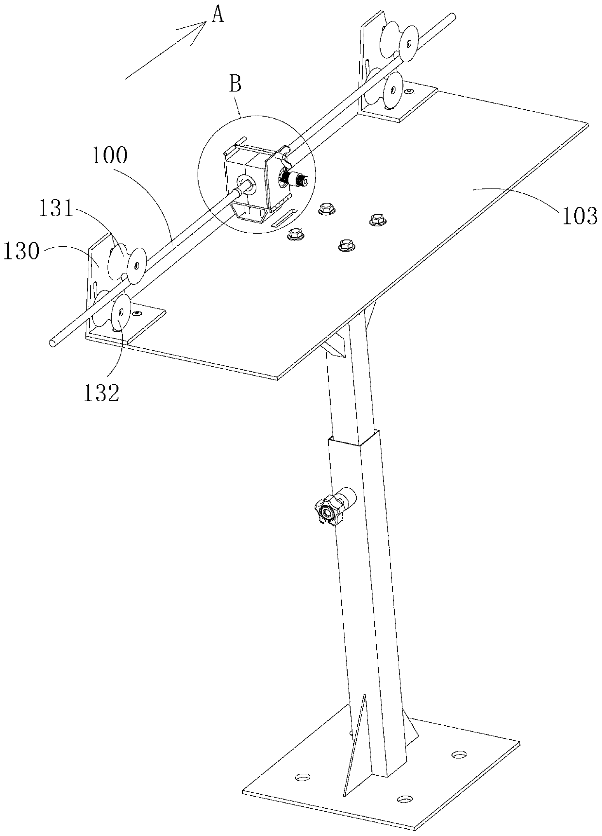
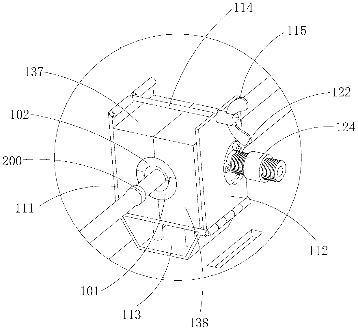
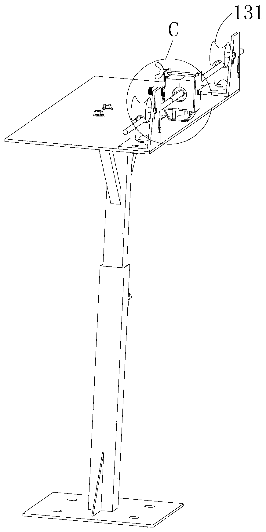
[0049] see Figure 1 to Figure 12 As shown, among them, figure 1 The arrow direction A in the figure refers to the moving direction of the cable 100. During the moving process, the position where the cable 100 passes first is defined as "front". In order to clearly describe the technical solution of this embodiment, figure 1 The cable 100 to be tested is shown in . This embodiment provides a cable package detection device, including a fixing device and a wire passing mold, the fixing device is provided with a limit hole for placing the wire passing mold; the wire passing mold includes a first half mold 101 and a second half mold 102, the first half-mold 101 and the second half-mold 102 are placed in the limit holes, and can be fastened to form a channel 106 for the cable 100 to pass through; when the width d of the package 200 on the surface of the cable is larger than the channel When the width w of 106, the package block 200 can be in contact with the front end faces of t...

Embodiment 2

[0094] see Figure 13 and Figure 14 As shown, this embodiment also provides a cable packet detection device. The cable packet detection device of this embodiment is an improvement on the basis of Embodiment 1. In addition, the technical solution of Embodiment 1 It also belongs to this embodiment and will not be described again here. The same components use the same reference numerals as in the first embodiment, and reference is made to the description of the first embodiment.

[0095] In order to be able to detect lumps in time and prevent the lumps from being entangled on the take-up reel as the cables move, the cable lump detection device provided in this embodiment also includes an alarm device. The alarm device includes a gap adjustment seat 135, a first reset switch S1, transmission rod 136, magnetic latching relay J and alarm L; one end of gap adjustment seat 135 is connected with elastic force adjustment seat 124, and the first reset switch S1 is installed on the oth...

Embodiment 3

[0104] see Figure 15 and Figure 16 As shown, this embodiment also provides a cable bundle detection device. The cable bundle detection device in this embodiment describes another connection method between the first clamping block 137 and the second clamping block 138. In addition The other technical solutions of Embodiment 1 also belong to this embodiment, and will not be described again here. The same components use the same reference numerals as in the first embodiment, and reference is made to the description of the first embodiment.

[0105] In some embodiments, the first clamping block 137 is provided with a first connecting portion, the second clamping block 138 is provided with a second connecting portion, and the first connecting portion is fixedly connected to the second connecting portion.

[0106] In a possible implementation, the first connecting part is the first mounting plate 141, the first mounting plate 141 is fixedly connected to the upper surface of the ...


PUM


Abstract

The invention relates to the technical field of cable production, in particular to cable block detection device. The cable block detection device comprises a fixing device and a cable passing die, wherein the fixing device is provided with a limit hole allowing placement of the cable passing die; the cable passing die comprises a first half die and a second half die, and the first half die and thesecond half die are placed in the limit hole and can be buckled to form a channel allowing a cable to pass through; when width of a block on the surface of the cable is larger than that of the channel, the block can be propped against the front end surfaces of the first half die and the second half die, the first half die and the second half die can be driven to move in the length direction of the limit hole, and therefore, the first half die and the second half die are broken away from the fixing device and are separated.According to the cable block detection device, the first half die and the second half die are placed in the fixing device, and can be immediately separated after being broken away from the fixing device, and the purpose of rapidly dismounting the cable penetrating die isachieved.

Description

technical field [0001] The invention relates to the technical field of cable production, in particular to a cable package detection device. Background technique [0002] In the cable production process, it is necessary to judge whether the outer diameter of the cable is uniform and whether there are lumps. At present, the main detection method is to set the wire-passing die on the cable take-up path, that is, the wire-passing die is set between the traction device and the take-up device, the wire-passing die is composed of two semi-cylindrical molds, Both grooves are provided with grooves, and the notches of the two grooves are opposite to form a round hole. The diameter of the round hole is roughly equal to the outer diameter of the cable to be tested, so that the cable can pass through. Wrap the two half-cylindrical molds together, then tape the ends to the brackets. If the impurity mass of the cable sheath is larger than the diameter of the round hole, the cable cannot ...

Claims


Application Information

Patent Timeline
Patent Type & Authority Applications(China)
IPC IPC(8): G01B3/34G01B5/04G01B5/10
CPCG01B3/34G01B5/046G01B5/10
Inventor 何新东赵现伟姜泽兴刘中奎李仲柳青任志鹏
Owner SHENYANG HENGTONG OPTICAL COMM CO LTD
Why Eureka
Try Eureka