
A feeding mechanism of a particle implantation device

A technology of implantation device and feeding mechanism, applied in the field of medical devices, can solve the problems of small particle clip, prolong operation time, increase operator's burden, etc. Effect

Active Publication Date: 2021-05-07
苏州奈维医疗科技有限公司
View PDF6 Cites 0 Cited by
  • Summary
  • Abstract
  • Description
  • Claims
  • Application Information

AI Technical Summary

Problems solved by technology

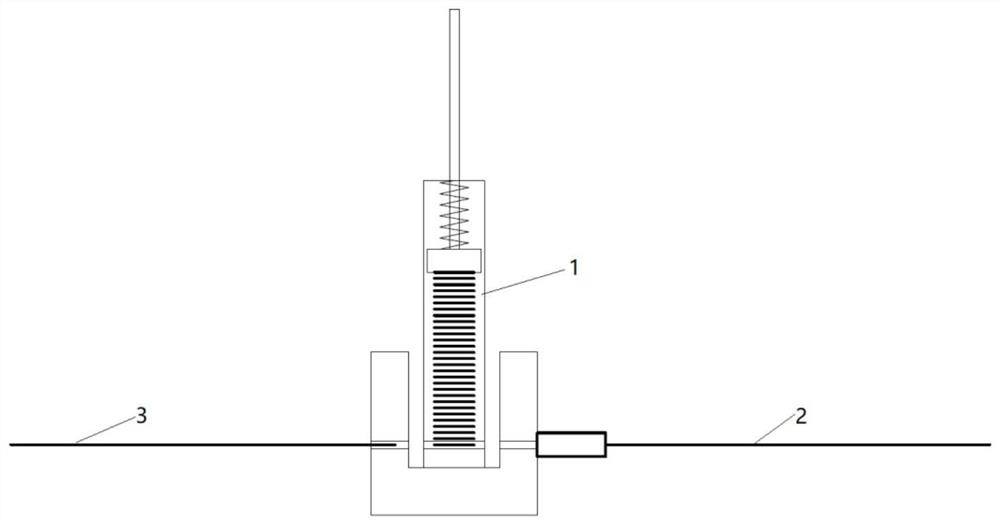
[0004] At present, the widely used particle implantation devices all have particle storage mechanisms—magazines. These devices generally have the following deficiencies: (1) The particle clips are small, and the particle clips need to be replaced frequently in operations that require more particles. Increase the burden on the operator and prolong the operation time; (2) The length direction of the particle clip 1 of the particle implantation device is arranged perpendicular to the axes of the puncture needle 2 and the push needle 3, such as figure 1 As shown, the radial dimension of the whole particle implantation device is larger, which brings inconvenience to the operation process of some lesion positions
[0005] In order to enable the particle clip to store enough particles, a way that those skilled in the art can easily think of is to increase the length of the particle clip, but since the length direction of the particle clip is perpendicular to the axis of the puncture needle, increasing the particle clip The length of the clamp increases the radial dimension of the particle implantation device accordingly, which is even more unfavorable for the operation of the operation.

Method used


Image

  • A feeding mechanism of a particle implantation device
  • A feeding mechanism of a particle implantation device
  • A feeding mechanism of a particle implantation device

Examples


Embodiment Construction

[0033] In order to make the above objects, features and advantages of the present invention more comprehensible, specific implementations of the present invention will be described in detail below in conjunction with the accompanying drawings. In the following description, many specific details are set forth in order to fully understand the present invention, but the present invention can be implemented in many other ways different from those described here, and those skilled in the art can do similar Modifications, and thus the present invention is not limited to the specific implementations disclosed below.

[0034] It should be noted that when an element is referred to as being “fixed” to another element, it can be directly on the other element or there can also be an intervening element. When an element is referred to as being "connected to" another element, it can be directly connected to the other element or intervening elements may also be present. As used herein, the ...


PUM


Abstract

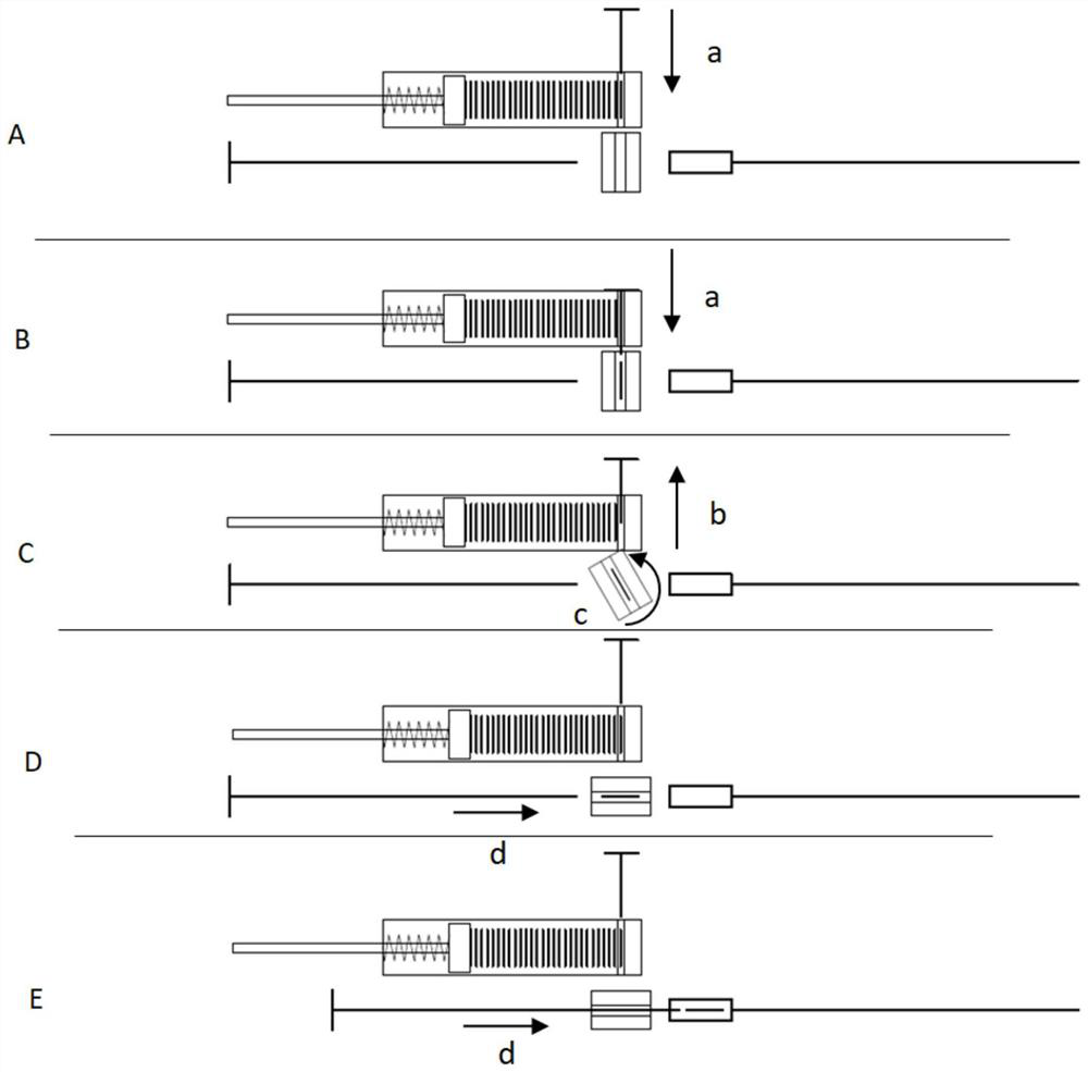
The invention provides a feeding mechanism of a particle implantation device. The feeding mechanism includes a particle clip. The particle clip includes a particle cover cylinder, a particle storage chamber and a particle driving part. The particle storage chamber includes a first end and an opposite end. At the second end, the particle driving part pushes the particles from the first end to the second end; the particle clip has a first particle channel at the second end, and the feeding mechanism includes a particle top piece that can move in the first particle channel; the particle bomb The length direction of the clip and the axial direction of the puncture needle are arranged in a non-perpendicular state; the feeding mechanism also includes a commutator, and the commutator has a second particle channel; the commutator has a first working position and a second working position. When the commutator is at the first working position, the first particle channel is coaxial with the second particle channel, and when the commutator is at the second working position, the second particle channel is coaxial with the push needle and the puncture needle. The present invention provides sufficient particles for the surgical procedure while allowing the particle implantation device to be compact in size.

Description

technical field [0001] The invention belongs to the field of medical devices, and in particular relates to a feeding mechanism of a particle implantation device. Background technique [0002] Implantation of radioactive seeds in the treatment of malignant tumors is a minimally invasive treatment method, which has broad application prospects in clinical practice. This method has the advantages of simple operation, less side effects, and good therapeutic effect. [0003] The radioactive material is implanted into the human body through the particle implantation device. The front end of the particle implantation device is connected with a puncture needle, and the rear end is connected with a push needle. During the operation, generally, a plurality of puncture needles are inserted into the patient's body in sequence according to predetermined penetration depths and positions, and then each puncture needle is operated one by one. When operating each puncture needle, first use ...

Claims


Application Information

Patent Timeline
Patent Type & Authority Patents(China)
IPC IPC(8): A61M36/12
CPCA61N5/1007A61N2005/1009A61N2005/101
Inventor 孙立宁王珏孙玉宁
Owner 苏州奈维医疗科技有限公司
Learn More