
Full yarn shearing mechanism

A technology of full yarn and scissors, which is applied in the cutting of textile materials, textile and papermaking, and the transportation of filamentous materials, etc. It can solve the problems of yarn grabbing failure and other problems, and achieve the effect of reasonable structure, simple design and high sensitivity

Pending Publication Date: 2019-06-11
绍兴职业技术学院
View PDF0 Cites 2 Cited by
  • Summary
  • Abstract
  • Description
  • Claims
  • Application Information

AI Technical Summary

Problems solved by technology

When the single spindle is full and stops, the stop position of the yarn relative to the drum is uncertain, and the yarn position is not within the grasping range, resulting in the failure of grasping the yarn. In view of this, this full yarn cutting device is specially developed.

Method used


Image

  • Full yarn shearing mechanism
  • Full yarn shearing mechanism

Examples


Embodiment Construction

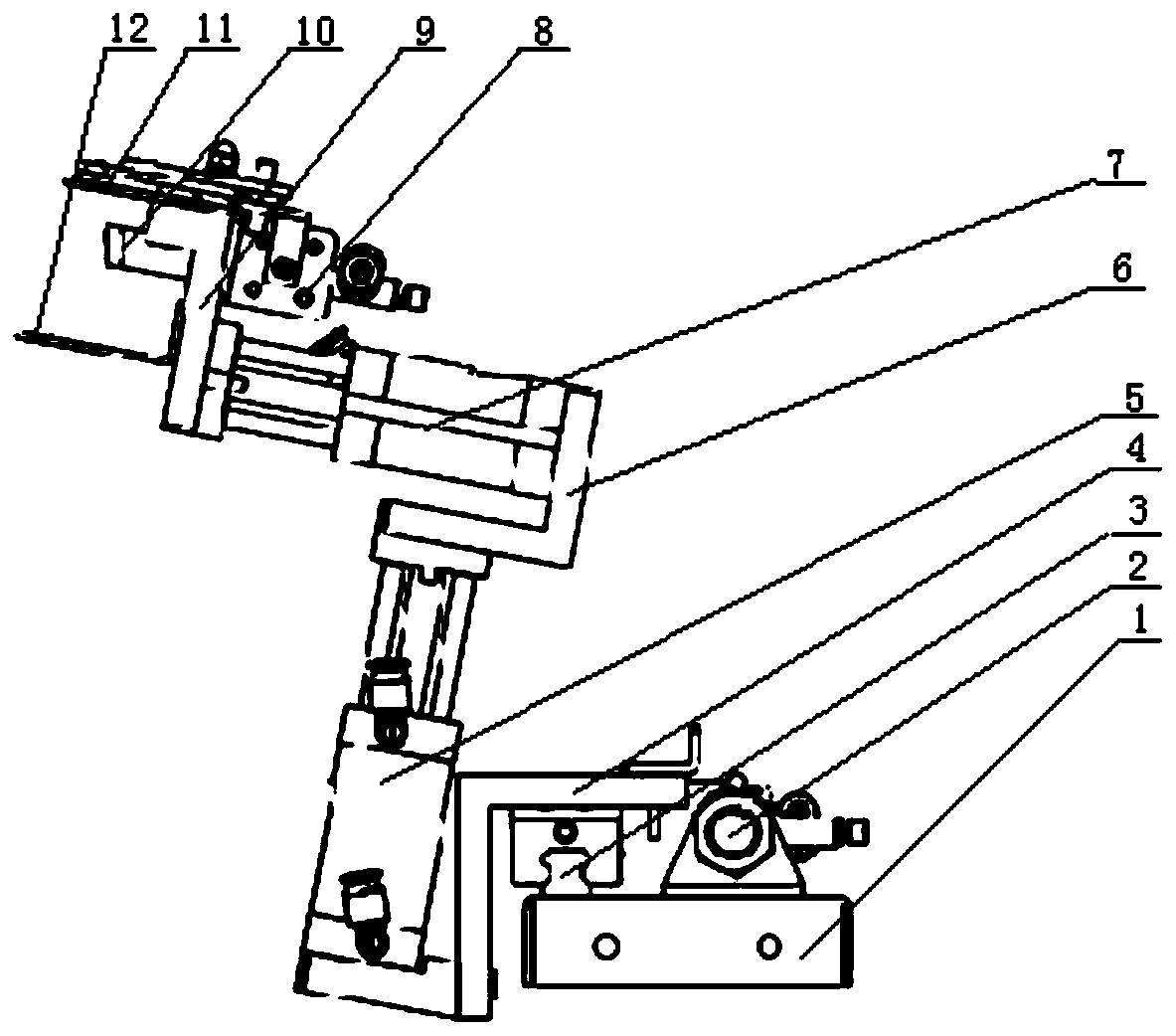
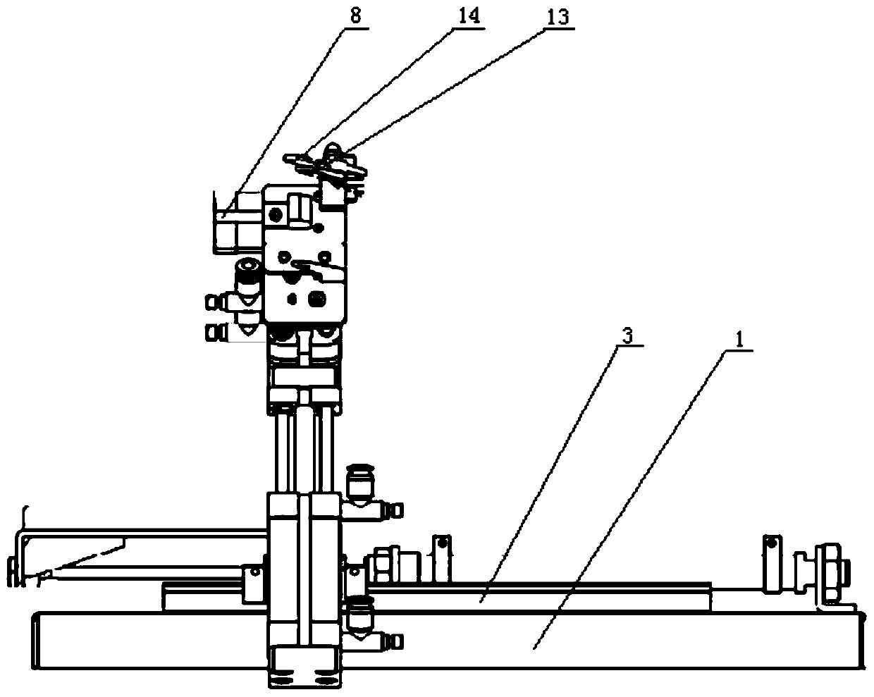
[0013] refer to Figure 1 to Figure 2 The specific implementation of a full yarn cutting mechanism of the present invention will be further described.

[0014] A full yarn cutting mechanism, comprising a base plate 1, the base plate 1 is provided with a guide rail 3 along the transverse direction, a connecting plate-4 is slidably connected to the guide rail 3, and the connecting plate-4 is provided on the base plate 1 to drive Sliding driving device one 2, the connecting plate one 4 is connected with a vertical cylinder one 5, the top of the cylinder one 5 is fixedly connected with a connecting plate two 6, and the connecting plate two 6 is fixedly equipped with a cylinder Two 7, the telescopic direction of the cylinder two 7 is perpendicular to the length direction of the base plate 1, the top of the cylinder two 7 is connected with a connecting plate three 9, and one side of the connecting plate three 9 is provided with a wire hook 10 and a suction Yarn port opening block 1...


PUM


Abstract

The invention discloses a full yarn shearing mechanism. The full yarn shearing mechanism comprises a bottom plate, wherein a guide rail is arranged on the bottom plate in the transverse direction, anda connecting plate I is slidably connected to the guide rail; a driving device I which drives the connecting plate I to slide is arranged on the bottom plate, and a vertical air cylinder I is connected to the connecting plate I; a connecting plate II is fixedly connected to the top end of the air cylinder I, and an air cylinder II is fixedly installed on the connecting plate II; the expansion direction of the air cylinder II is perpendicular to the length direction of the bottom plate, and a connecting plate III is connected to the top end of the air cylinder II; a wire hook and a yarn suction opening block are arranged on one side of the connecting plate III, and a scissor device is arranged on the connecting plate III; and the scissor device is connected with a driving device II which drives the scissor device to be closed and opened. According to the full yarn shearing mechanism, when a tube yarn is grabbed above a yarn guide plate of a yarn cleaner, the yarn can be assisted to enter the yarn shearing position and the yarn clamping position of a grabbing device quickly and accurately, and the full yarn shearing link is skillfully completed; and the design is easy, the structureis reasonable, the difficult problem of yarn grabbing failure due to the fact that the yarn position is not in the grabbing range can be overcome.

Description

technical field [0001] The invention relates to the technical field of textile machinery, and more specifically relates to a full yarn cutting mechanism. Background technique [0002] Winding refers to the technological process of rewinding bobbins and skeins into various forms of bobbins. In the traditional winding process, there is a yarn cutting process. When a single spindle is full, the yarn needs to be cut and replaced. When the single spindle is full and stops, the stop position of the yarn relative to the drum is uncertain, and the yarn position is not within the grasping range, resulting in the failure of grasping the yarn. In view of this, this full yarn cutting device is specially developed. . Contents of the invention [0003] Aiming at the deficiencies of the prior art, the present invention provides a full yarn cutting mechanism, which can assist the yarn to enter the cutting device of the grabbing device quickly and accurately when grabbing the bobbin yarn ...

Claims


Application Information

Patent Timeline
Patent Type & Authority Applications(China)
IPC IPC(8): B65H67/08D06H7/00
Inventor 祝新军裘升东周玮
Owner 绍兴职业技术学院
Learn More