
Objective lens drive device and optical disk device

A technology for a driving device and an objective lens, which is applied in the configuration/installation of the head, recording/reproducing by optical methods, instruments, etc., and can solve the problems of deterioration of light spot aberration, influence of recording and playback, etc.

Inactive Publication Date: 2004-05-19
PANASONIC CORP
View PDF1 Cites 1 Cited by
  • Summary
  • Abstract
  • Description
  • Claims
  • Application Information

AI Technical Summary

Problems solved by technology

Therefore, on the movable part 64 that includes the objective lens 51, owing to produce the rotational vibration that takes the tracking direction Tr as the axis, that is, the so-called pitching vibration (pitching vibration), so the aberration of the light spot is deteriorated, and the recording and reproduction are affected. The problem

Method used


Image

  • Objective lens drive device and optical disk device
  • Objective lens drive device and optical disk device
  • Objective lens drive device and optical disk device

Examples


Embodiment Construction

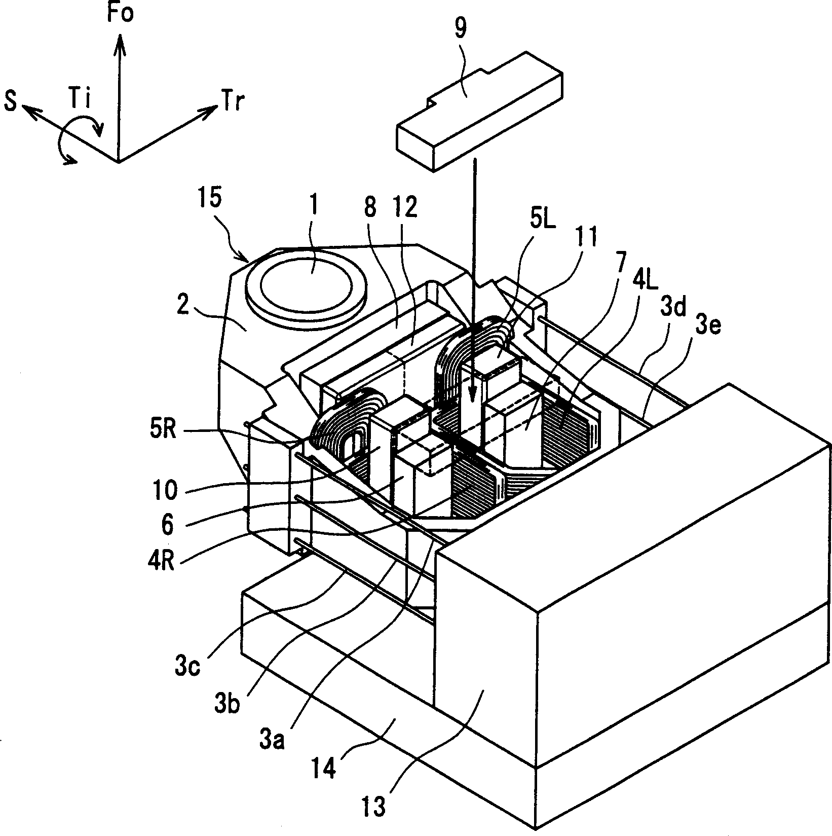
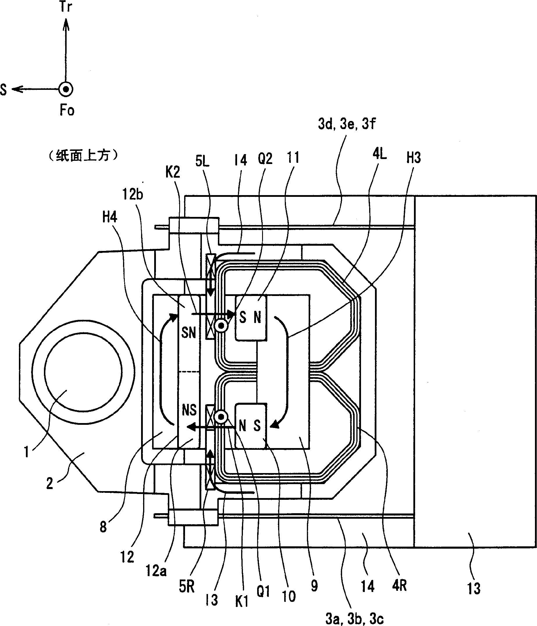
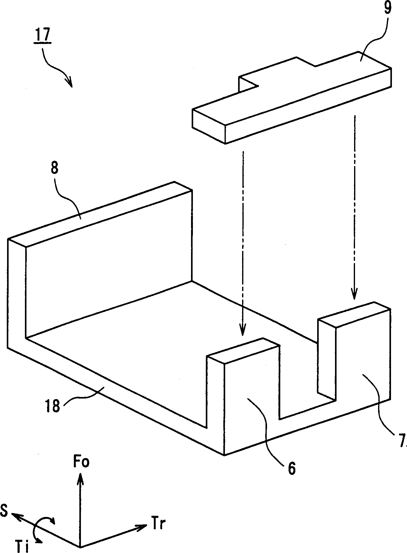
[0021] Since the objective lens driving device of the present invention has a bridge yoke connecting the open end of the first yoke and the open end of the second yoke, it is possible to prevent leakage that crosses the focus coil between the first yoke and the second yoke. Magnetic flux. Therefore, the pitch vibration of the movable part can be suppressed. In addition, since the magnetic utilization efficiency can be improved, the focus driving sensitivity can be improved.

[0022] In addition, because the bridge yoke is configured to not interfere with the tracking coil, the effective length of the tracking coil is not reduced, and the thickness of the objective lens driving device is not increased, and the tracking driving sensitivity can be improved.

[0023] In the objective lens driving device of the present invention described above, the third magnet and the fourth magnet are preferably held by a common third yoke arranged outside the magnetic gap, so that the generation of...


PUM


Abstract

Tracking coils are attached to outer surfaces of two focusing coils. Inside the focusing coils, a first magnet and a second magnet are arranged respectively. A third magnet is arranged so as to face the first magnet and the second magnet via the tracking coils. An open end of a first yoke for holding the first magnet and an open end of a second yoke for holding the second magnet are connected by a bridging yoke. Since a magnetic flux is formed in the bridging yoke, pitching vibrations can be suppressed and a driving sensitivity improves owing to an increase in an effective magnetic flux.

Description

Technical field [0001] The present invention relates to an objective lens driving device, and more particularly to an objective lens driving device used in a recording and reproducing device that irradiates a light spot on a disc-shaped recording medium to optically record and / or reproduce information. In addition, the present invention relates to an optical disc device having such an objective lens driving device. Background technique [0002] The conventional objective lens drive device drives the objective lens that forms a light spot on the disc recording surface in the direction perpendicular to the disc surface (hereinafter referred to as the "focus direction") and the radial direction of the disc (hereinafter referred to as the "tracking direction"). . In an optical disc device corresponding to higher density, in order to obtain good recording and reproducing characteristics, a function of correcting optical coma (comaaberration) is added. In order to achieve this function...

Claims


Application Information

Patent Timeline
Patent Type & Authority Applications(China)
IPC IPC(8): G11B7/09G11B7/095
CPCG11B7/0935G11B7/0956G11B7/0933
Inventor 井川喜博山本宽家木浩二
Owner PANASONIC CORP
Learn More