
DC motor

A technology of DC motors and casings, which is applied in the direction of electrical components, electromechanical devices, electric components, etc., can solve the problems of low production efficiency, cumbersome and complicated process, and high defective rate, and achieve the effect of improving production efficiency

Inactive Publication Date: 2021-02-09
艾博金电气制造(深圳)有限公司
View PDF6 Cites 0 Cited by
  • Summary
  • Abstract
  • Description
  • Claims
  • Application Information

AI Technical Summary

Problems solved by technology

In this way, the process is cumbersome and complicated, the production efficiency is low, and the defective rate is high, which leads to an increase in production costs

Method used


Image

  • DC motor
  • DC motor
  • DC motor

Examples


Embodiment Construction

[0020] The present invention will be described in detail below in conjunction with the accompanying drawings and specific embodiments, so as to make the technical solution and beneficial effects of the present invention clearer. It can be understood that the drawings are only for reference and description, and are not used to limit the present invention. The dimensions shown in the drawings are only for the convenience of clear description, and do not limit the proportional relationship.

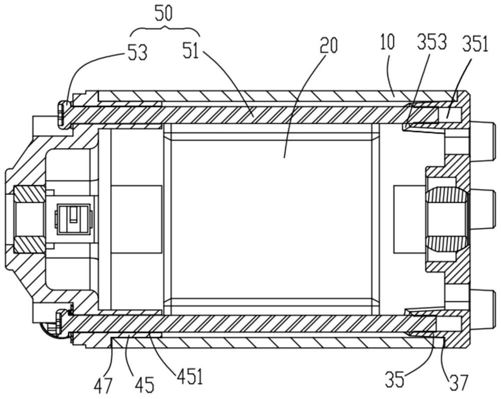
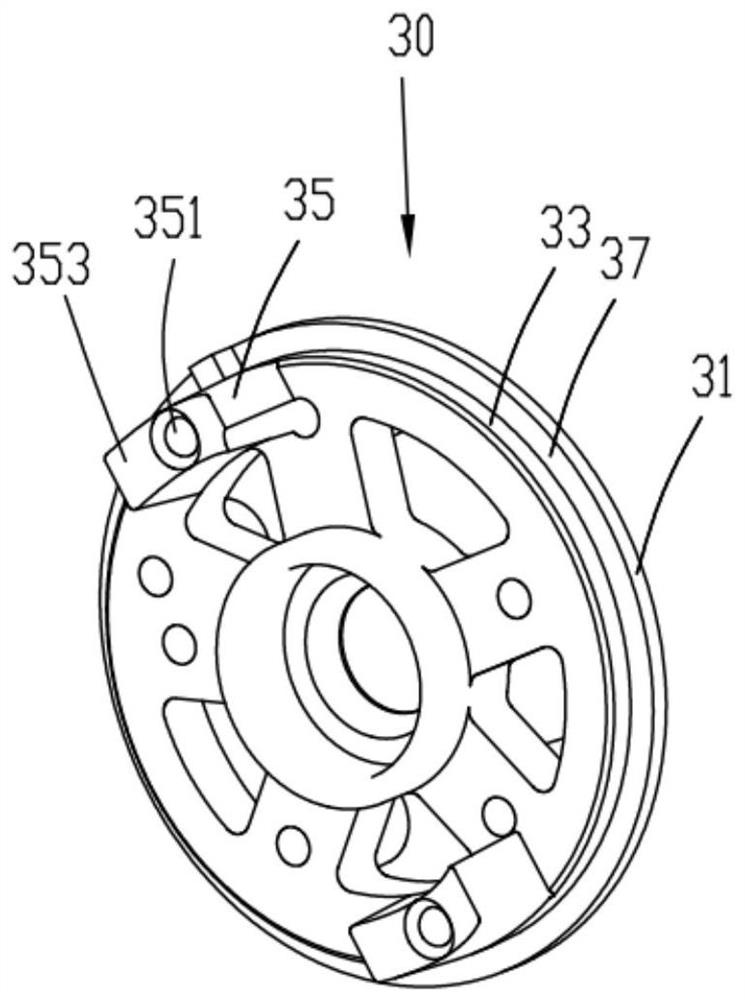
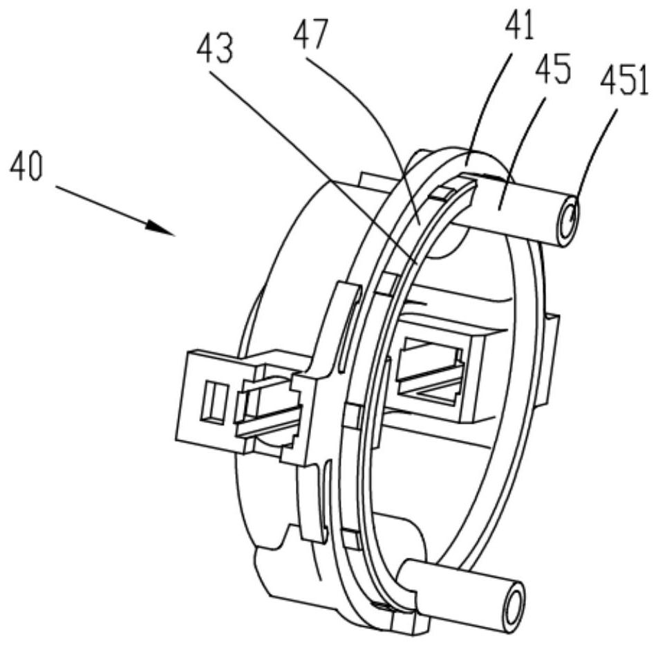
[0021] refer to Figure 2 to Figure 3 A DC motor according to an embodiment of the present invention includes a casing 10, an iron core 20 housed in the casing 10, a front end cover 30 positioned at opposite ends of the casing 10, a rear end cover 40, and a fixed casing 10 and the front end cover 30 and Long screw 50 of rear end cap 40 .

[0022] The front cover 30 includes a front base 31 , a front boss 33 protruding from a side surface of the front base 31 toward the rear end cover 40 , a...


PUM


Abstract

A direct current motor comprises a casing, an iron core accommodated in the casing, a rear end cover and a front end cover which are located at the relative two ends of the casing, and a long screw used for fixing the rear end cover and the front end cover on the casing. The rear end cover protrudes towards the front end cover to form a rear guide portion, and the front end cover protrudes towardsthe rear end cover to form a front guide portion. The front guide portion and the rear guide portion are both located in the casing, are oppositely arranged, protrude and extend in the opposite directions and allow the long screw to penetrate through. According to the invention, because the front guide part of the front end cover and the rear guide part of the rear end cover protrude oppositely,the long screw can enter a gap between the iron core and the casing vertically after entering a rear guide hole and then can enter the front guide part accurately and rapidly, so that the direct-current motor can be fixed accurately and rapidly without auxiliary work, the production efficiency is greatly improved, and meanwhile, the quality of the direct-current motor is also improved.

Description

technical field [0001] The invention relates to the technical field of motors, in particular to a DC motor. Background technique [0002] A traditional DC motor includes a housing, a stator housed in the housing, a rotating shaft cooperating with the stator, and front and rear end covers located at opposite ends of the housing. Long screws pass through the stator from the rear end cover and cooperate with the threaded holes provided on the front end cover, thereby fixing the front and rear end covers. However, when the long screw passes through the stator, it is easy to attract the long screw to one side due to the strong magnetism of the inner iron core, thus causing it to deviate from the threaded hole of the front end cover. In this case, it is necessary to use a manipulator or other auxiliary fixtures to fix the long screw and correct its position, and then use a tool to pinch the long screw. Such operations lead to cumbersome and complicated processes, low production ...

Claims


Application Information

Patent Timeline
Patent Type & Authority Applications(China)
IPC IPC(8): H02K5/04H02K5/16
CPCH02K5/04H02K5/161
Inventor 刘龙波张富平陈诚李政林石广全王乐陈华信
Owner 艾博金电气制造(深圳)有限公司
Learn More