Locking nut machine

A lock nut machine and lock nut technology, applied in metal processing, metal processing equipment, manufacturing tools, etc., can solve the problems of low labor efficiency and low lock nut precision, and achieve the effect of saving labor, realizing automatic control and improving efficiency

Inactive Publication Date: 2019-11-19
吴巧
View PDF8 Cites 0 Cited by
  • Summary
  • Abstract
  • Description
  • Claims
  • Application Information

AI Technical Summary

Problems solved by technology

[0003] In order to solve the problems of low lock nut precision and low labor efficiency in the prior art, the invention provides a lock nut machine, which has the characteristics of precise lock nut and high operating efficiency.

Method used


Image

  • Locking nut machine
  • Locking nut machine
  • Locking nut machine

Examples


Embodiment Construction

[0027] In order to make the purpose, technical solution and advantages of the present invention clearer, the technical solution of the present invention will be described in detail below. Apparently, the described embodiments are only some of the embodiments of the present invention, but not all of them. Based on the embodiments of the present invention, all other implementations obtained by persons of ordinary skill in the art without making creative efforts fall within the protection scope of the present invention.

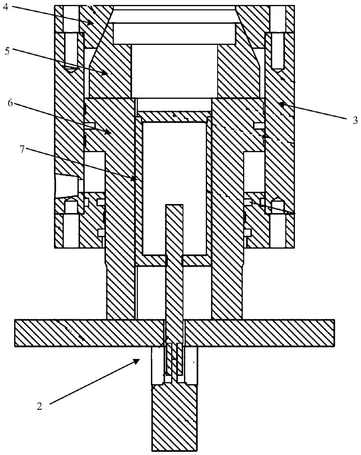
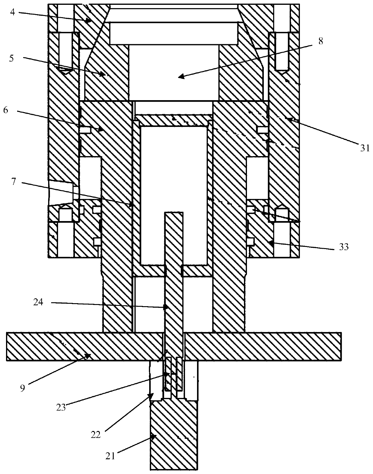
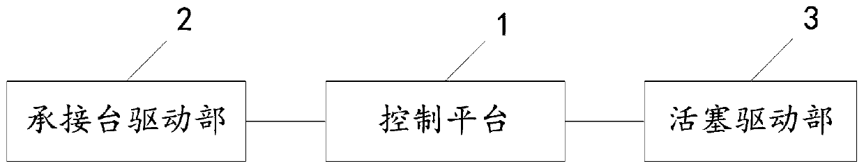
[0028] refer to figure 1 with image 3 The illustrated embodiment of the present invention provides a lock nut machine, comprising: a control platform 1, a piston 6 and a receiving platform 7;

[0029] A limit flange 4 is arranged along the movement direction of the piston 6, and the end of the piston 6 close to the limit flange 4 is provided with a lock nut clamping block 5. When the piston 6 moves toward the limit flange 4, the limit flange 4 Make the claws...


PUM


Abstract

The invention relates to a locking nut machine. A limiting flange is arranged in the moving direction of a piston, a locking nut clamping block is arranged at the end, close to the limiting flange, ofthe piston, and when the piston moves towards the limiting flange, the limiting flange makes clamping claws of the locking nut clamp move in the direction perpendicular to the moving of the piston toclamp a put-in locking nut. A carrying table is sleeved with the piston and used for carrying the locking nut, and the carrying table is driven by a carrying table driving part to move in the direction identical with the moving direction of the piston. The limiting flange, the locking nut clamping block, the piston and the carrying table define a locking nut containing space. A control platform obtains locking nut placing depth and locking nut outer diameter dimension data and then controls the bearing table driving part and a piston driving part to make the carrying table move to the assigned depth and the locking claws of the locking nut clamping block form the inner diameter dimension identical with the outer diameter dimension of the locking nut. A user only needs to input needed depth and the locking nut outer diameter, data adjusting can be automatically achieved, automatic control over locking nut clamping is achieved, and efficiency is improved.

Description

technical field [0001] The invention belongs to the technical field of mechanical manufacturing, and in particular relates to a lock nut machine. Background technique [0002] Pipe joints are inseparable from the manufacturing process of hydraulic, pneumatic transmission and other equipment. During the production process of joints, nuts need to be buckled on the pipe joints. The current traditional method is to manually adjust the depth of the pipe. And the outer diameter of the clamping device not only requires a lot of manual labor, but also leads to inaccurate placement of the lock nut, which cannot guarantee the accuracy of the product, so the manual operation method can no longer meet the needs of today's development. Contents of the invention [0003] In order to solve the problems of low lock nut precision and low labor efficiency in the prior art, the present invention provides a lock nut machine, which has the characteristics of precise lock nut and high operating...

Claims


Application Information

Patent Timeline
Patent Type & Authority Applications(China)
IPC IPC(8): B23P19/06
CPCB23P19/061
Inventor 吴巧武献昌
Owner 吴巧
Why Eureka
Try Eureka