Standard signal generator

a technology of signal generator and generator, which is applied in the direction of instruments, measurement devices, volume/mass flow measurement, etc., can solve the problems of affecting the accuracy of measurement, and unable to house large components such as the excitation coil of the detector b>1/b>, so as to reduce the power source voltage, suppress heat generated, and increase the power source voltage

Active Publication Date: 2019-02-26
YAMATAKE HONEYWELL CO LTD
View PDF11 Cites 0 Cited by
  • Summary
  • Abstract
  • Description
  • Claims
  • Application Information

AI Technical Summary

Benefits of technology

[0024]According to the present invention, it becomes possible to drive a standard signal generator without a battery by using an excitation current supplied from a converter to generate a power source voltage. Accordingly, the problem of it not being possible to perform calibration work due to a battery running out is resolved. Furthermore, in the present invention, the power source voltage can be switched by controlling the constant voltage circuit in accordance with the result of a comparison between the first output voltage and the prescribed first threshold value. Accordingly, with the present invention, it is possible to increase the power source voltage when the converter connected to the standard signal generator is a converter of a two-wire electromagnetic flowmeter, and therefore the power required for the operation of the standard signal generator can be supplied without any problems, and the occurrence of trouble such as the operation of the standard signal generator stopping due to a power supply shortage no longer occurs. Furthermore, in the present invention, it is possible to decrease the power source voltage when the converter connected to the standard signal generator is a converter of a four-wire electromagnetic flowmeter, and it is therefore possible to suppress heat generated by the standard signal generator and to suppress temperature drifts in electrical circuits due to internal heat generation, and it is subsequently possible to reduce the impact on the performance of the standard signal generator caused by temperature drifts.
[0025]Furthermore, in the present embodiment, when the first output voltage is compared with the prescribed second threshold value and it is determined that there is a current supply shortage with the excitation current, the supply source of the power source voltage is switched from the constant voltage circuit of the input circuit to the battery, and it is thereby possible to prevent the occurrence of a shortage of the power required for the operation of the standard signal generator. In the present invention, it is possible to eliminate the occurrence of trouble such as the operation of the standard signal generator stopping due to a power supply shortage even when the excitation current is within a lower range of the current supplied from the converter of a two-wire electromagnetic flowmeter. Furthermore, a power source voltage is supplied from the battery in an excitation current pause period, and therefore it is possible to eliminate the occurrence of trouble such as the operation of the standard signal generator stopping even when the pause period is long. Furthermore, in the present invention, power is not supplied from the battery when the excitation current is within a range of the current supplied from the converter of a four-wire electromagnetic flowmeter or is within a lower range or greater of the current supplied from the converter of a two-wire electromagnetic flowmeter, and therefore the consumption of the battery is able to be greatly reduced compared to the case where only a battery is used as a power source as in a conventional standard signal generator.
[0026]Furthermore, in the present invention, by providing the first rectification circuit, the first resistor, and the amplification circuit in the input circuit of the standard signal generator, the excitation current is able to be accurately measured at the control means side, and therefore the setting of the model of converter can be automated.
[0027]Furthermore, in the present invention, it is possible to output a highly precise first output voltage that is proportional to the magnitude of the excitation current, it is possible to generate a reference flow-rate signal that corresponds to the value of the excitation current and output the reference flow-rate signal to the converter, and it is possible to realize the calibration of a two-wire electromagnetic flowmeter within a total flow-rate measurement range.
[0028]Furthermore, in the present invention, by providing the second rectification circuit, the second resistor, the third rectification circuit, and the third resistor in the input circuit of the standard signal generator, the polarity of the excitation current is able to be accurately detected.

Problems solved by technology

The flow-rate signal that is input from the detector 1 to the converter 2 is a very small μV-order signal, and therefore measurement precision is liable to deteriorate due to changes that occur with the aging of the electrical components used in the converter 2.
It is necessary for the calibrator 3 to be small and lightweight such that work can be easily carried out at the installation site, and therefore it is not possible for large components such as the excitation coil of the detector 1 to be housed therein.

Method used


Image

  • Standard signal generator
  • Standard signal generator
  • Standard signal generator

Examples


first embodiment

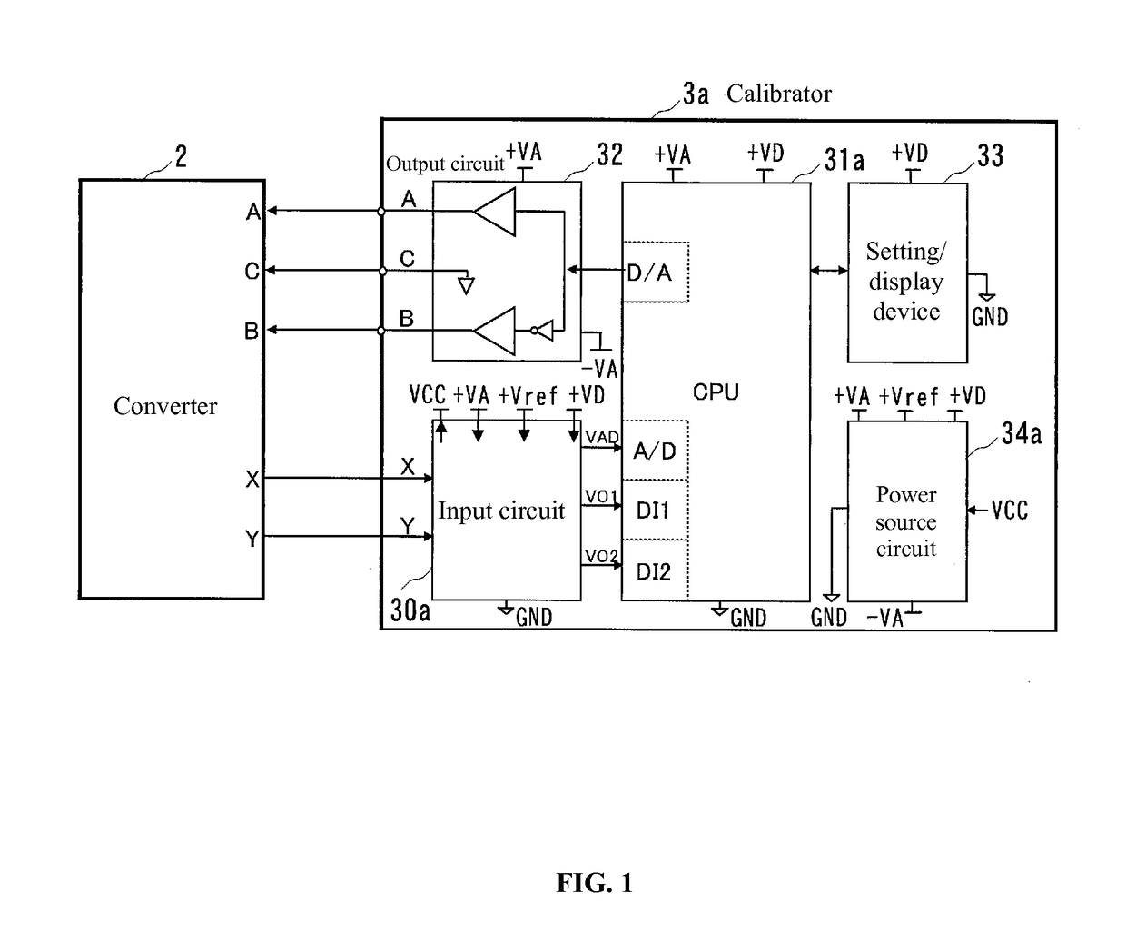
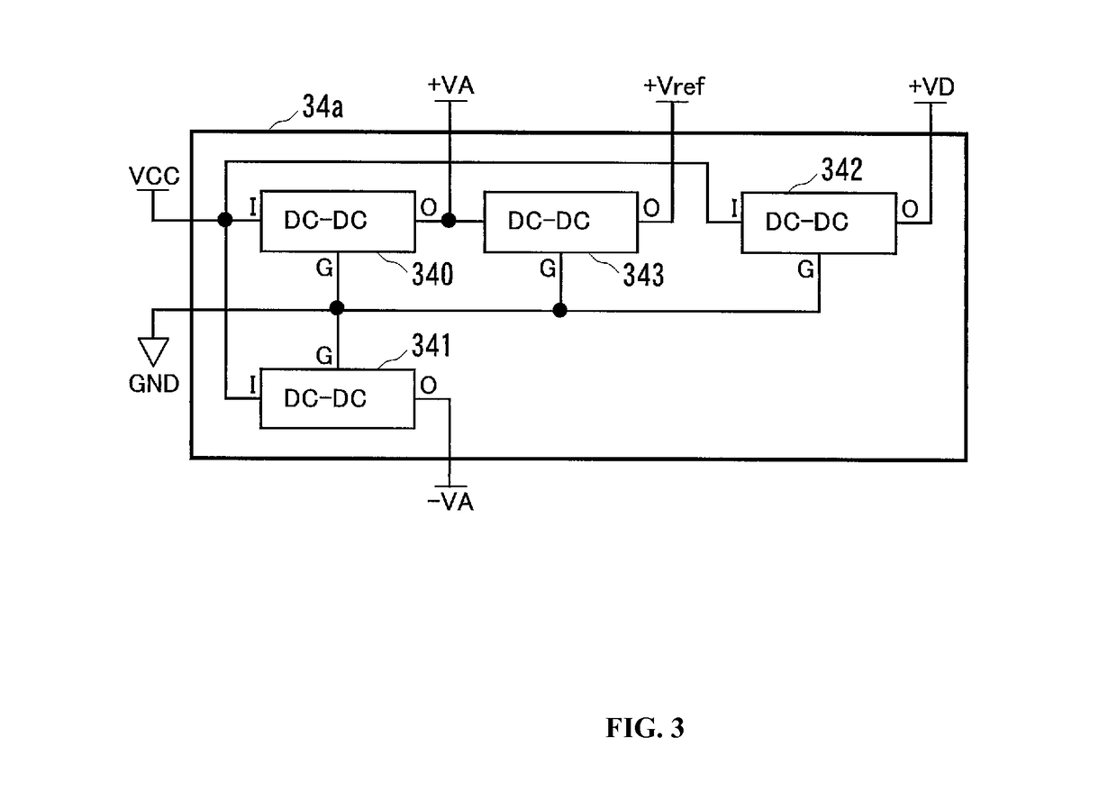
[0045]Hereinafter, embodiments of the present invention will be described with reference to the drawings. FIG. 1 is a block diagram illustrating the configuration of a calibrator according to a first embodiment of the present invention, and the same reference numerals are appended to the same components as in FIG. 13(A). A calibrator 3a of the present embodiment is configured from: an input circuit 30a which receives an excitation current that is input from a converter 2; a CPU 31a which is a control means that generates a reference flow-rate signal synchronized with the excitation current; an output circuit 32 which converts the reference flow-rate signal output from the CPU 31a into a differential signal and outputs the differential signal to the converter 2; a setting / display device 33 for setting the calibrator 3a and displaying information to a calibration worker; and a power source circuit 34a.

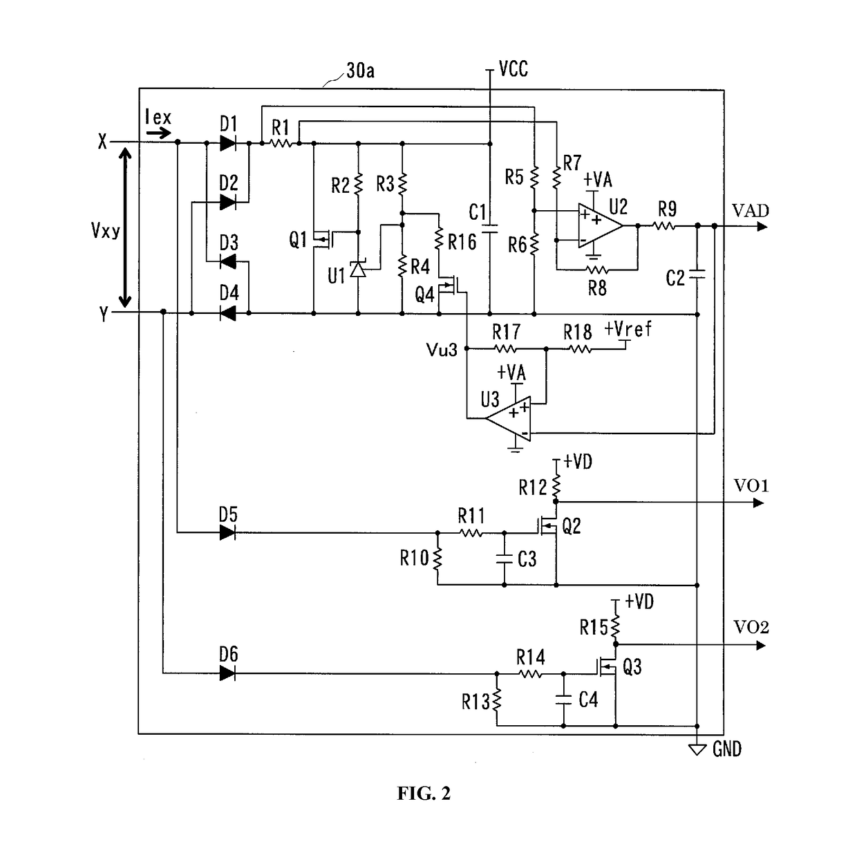
[0046]FIG. 2 is a circuit diagram illustrating the configuration of the input circu...

second embodiment

[0090]Next, a second embodiment of the present invention will be described. FIG. 10 is a block diagram illustrating the configuration of a calibrator according to the second embodiment of the present invention, and the same reference numerals are appended to the same components as in FIG. 1. A calibrator 3b of the present embodiment is configured from an input circuit 30b, the CPU 31a, the output circuit 32, the setting / display device 33, the power source circuit 34a, the battery 35, and a switch SW1. The operations of the CPU 31a, the output circuit 32, the setting / display device 33, and the power source circuit 34a are as described in the first embodiment.

[0091]FIG. 11 is a circuit diagram illustrating the configuration of the input circuit 30b of the present embodiment, and the same reference numerals are appended to the same components as in FIG. 2. The input circuit 30b is configured from: the diodes D1 to D6; the shunt regulator U1; the operational amplifier U2; the comparator...


PUM


Abstract

To realize a stable operation and the suppression of heat generation in the case where an excitation current supplied from a converter is used to generate a power source voltage, a standard signal generator is provided. The standard signal generator includes an input circuit that includes: a rectification circuit that rectifies an excitation current; a resistor that is provided between a power source voltage output terminal for supplying a power source voltage and an output terminal of the rectification circuit; an amplification circuit that outputs an output voltage obtained by amplifying a voltage across both ends of the resistor; and a constant voltage circuit that performs control such that the power source voltage is constant. A power source voltage switch switches the power source voltage with the constant voltage circuit being controlled in accordance with the result of a comparison between the output voltage and a prescribed threshold value.

Description

CROSS-REFERENCE TO RELATED APPLICATION[0001]The present application claims the benefit of, and priority to, Japanese Patent Application No. 2014-218951, filed on Oct. 28, 2014, the entire contents of which are incorporated by reference herein.[0002]The present invention relates to a standard signal generator for calibrating a converter of an electromagnetic flowmeter.BACKGROUND ART[0003]FIG. 12(A) is a block diagram illustrating the configuration of a conventional electromagnetic flowmeter. The electromagnetic flowmeter is configured from a detector 1 and a converter 2. The detector 1 is configured from an excitation coil 10 that generates a magnetic field, and a measurement tube 11 that is arranged in the magnetic field generated from the excitation coil 10, and that detects an electromotive force generated by a measurement-target fluid flowing through this magnetic field, and outputs a flow-rate signal that is proportional to the flow velocity thereof. The converter 2 supplies an ...

Claims


Application Information

Patent Timeline
Patent Type & Authority Patents(United States)
IPC IPC(8): G01F1/60G01F25/00
CPCG01F1/60G01F25/0007G01F25/10
Inventor MOMOSE, OSAMU
Owner YAMATAKE HONEYWELL CO LTD
Why Eureka
Try Eureka