
Upper reinforcing assembly for vehicle body B pillar

A technology for strengthening components and B-pillars, which is applied to vehicle components, superstructures, and sub-assemblies of the superstructure, and can solve problems such as uneven paths, large body deformation, and difficulty in opening doors.

Pending Publication Date: 2019-11-19
SAIC-GM-WULING AUTOMOBILE CO LTD
View PDF0 Cites 0 Cited by
  • Summary
  • Abstract
  • Description
  • Claims
  • Application Information

AI Technical Summary

Problems solved by technology

[0005] The present invention is completed in order to solve the deficiencies in the prior art. The purpose of the present invention is to provide a method that effectively solves the problem that the path between the load is transmitted to the upper end of the B-pillar assembly and the top beam is not smooth during a side collision, and ensures the load transmission path. Smooth, helps to disperse the load, avoiding the large deformation of the body caused by the concentration of force, which will cause the large deformation of the upper side beam area of ​​​​the side door of the body, making it difficult to open the door, and affecting the rescue of people in the car. Body B-pillar upper reinforcement components

Method used


Image

  • Upper reinforcing assembly for vehicle body B pillar
  • Upper reinforcing assembly for vehicle body B pillar
  • Upper reinforcing assembly for vehicle body B pillar

Examples


Embodiment Construction

[0033] The following with attached Figure 4 to Figure 9 A B-pillar upper reinforcement assembly of a vehicle body of the present invention is further described in detail.

[0034] A kind of vehicle body B-pillar upper reinforcement assembly of the present invention, please refer to Figure 4 to Figure 9As shown, it includes a B-pillar inner panel 3, a top beam 1, a B-pillar connecting plate 4, an upper side sill inner panel 2 and an A-pillar upper reinforcement panel 5, and the side part of the upper side sill inner panel 2 is laterally extended and fixed on the B-pillar Inside the upper end of the pillar inner panel 3, the A-pillar upper reinforcement plate 5 extends laterally and is fixed on the inner side of the upper side sill inner panel 2, the roof beam 1 is longitudinally fixed on the top cover 17, and the end of the roof beam 1 is connected to The upper end of the B-pillar inner panel 3 is fixed, the upper end of the B-pillar connecting plate 4 is fixed to the head o...


PUM


Abstract

The invention discloses an upper reinforcing assembly for a vehicle body B pillar. The upper reinforcing assembly comprises B pillar inner plates, top beams, B pillar connecting plates, upper edge beam inner plates and A pillar upper reinforcing plates; the side edge parts of the upper edge beam inner plates transversely extend to be fixed to the inner sides of the upper end parts of the B pillarinner plates, and the lower end parts of the B pillar connecting plates are fixed to the outer sides of the upper end parts of the corresponding B pillar inner plates; and inward-protruded protrusionparts are arranged in the middles of the B pillar connecting plates, and closed cavity structures are defined by the outer surfaces of the inner sides of the protrusion parts, the outer surfaces of the corresponding upper edge beam inner plates, the outer surfaces of the corresponding A pillar upper reinforcing plates and the outer surfaces of the corresponding top beams. According to the upper reinforcing assembly for the vehicle body B pillar, the problem that during side impact, loads are transmitted to the upper end of a B pillar assembly and then are unsmooth on a top beam path is effectively solved, the smoothness of the load transmitting path is ensured, the cavity structures are conducive to dispersion of the loads, and the situations that the vehicle body deformation is large dueto stress concentration, consequently deformation of upper edge beam areas of side doors of a vehicle body is large, the vehicle doors are difficult to open, and rescue of personnel in a vehicle is influenced are avoided.

Description

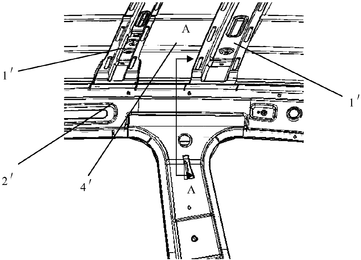
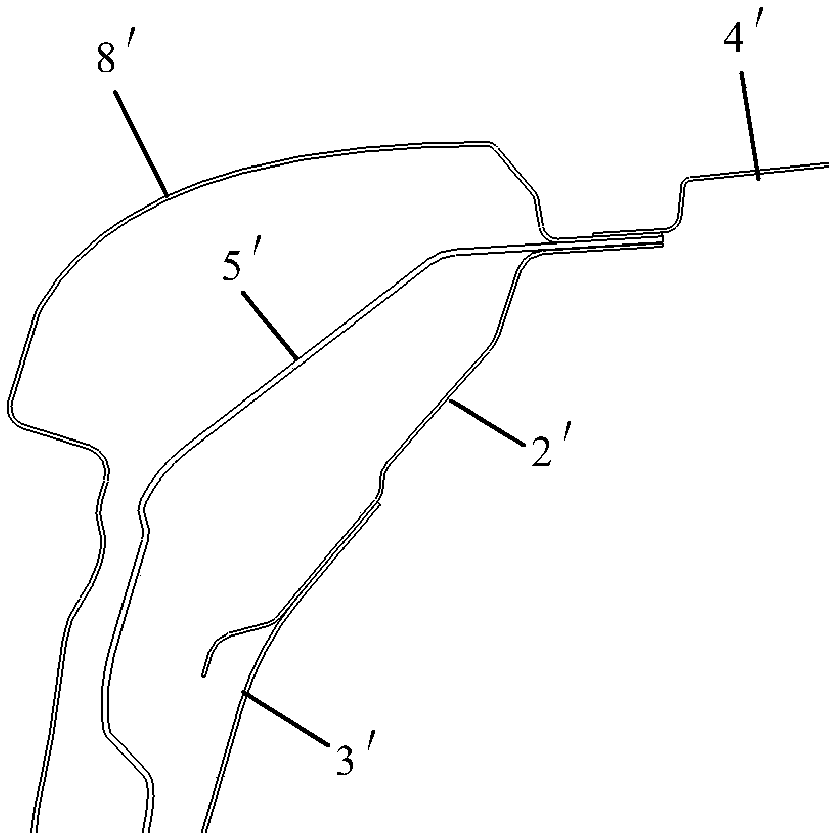
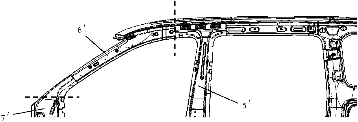
technical field [0001] The invention relates to a reinforcement assembly connected with a B-pillar of a vehicle body, in particular to an upper reinforcement assembly of a B-pillar of a vehicle body which strengthens the connection strength of the upper part of the B-pillar. Background technique [0002] The B-pillar structure of the body plays a key role in the torsional rigidity and collision safety of the body, especially the safety of side collisions. In the torsional condition of the body, the B-pillar structure affects the deformation of the body. The collision plays a role in reasonably absorbing the collision energy and protecting the safety of the occupants. The traditional B-pillar structure has the following problems: [0003] 1. If figure 1 and figure 2 As shown, the end of the traditional structure top beam 1' is fixed on the upper side sill inner panel 2', the upper end of the B-pillar inner panel 3' and the end of the top beam 1' are misaligned, and the to...

Claims


Application Information

Patent Timeline
IPC IPC(8): B62D25/04
CPCB62D25/04
Inventor 覃鹏飞郭平谢贵山钟巧波甘博卢堃林曾凤
Owner SAIC-GM-WULING AUTOMOBILE CO LTD
Learn More