
Roller case conveying method and apparatus used for electronic component package conveyor tape

A technology for electronic components and conveying devices, applied in the directions of transportation and packaging, conveyors, winding strips, etc., which can solve the damage to the electronic components of the coil, the complicated structure and procedures, the power consumption of the motor and the high cost of itself, etc. question

Inactive Publication Date: 2016-12-14
ALL RING TECH CO LTD
View PDF8 Cites 7 Cited by
  • Summary
  • Abstract
  • Description
  • Claims
  • Application Information

AI Technical Summary

Problems solved by technology

[0004] The prior art No. M467655 adopts a design in which a plurality of empty coils are stacked horizontally on the disc setting mechanism, and must be taken out one by one and the taken out empty coils are turned over from horizontal placement to a vertical direction by a preset disc mechanism. It is complicated in structure and procedure; and put the finished reel on the inclined tray plate for stacking, and each time a coil is dropped, the inclined tray plate will be lowered by one position, which is used to drive the inclined tray plate to descend intermittently. The driving force of the motor must be sufficient to bear the total weight of almost all the stacked reels that have completed the winding of the carrier tape, so that the power consumption of the motor and its own cost remain high
And the finished reel is tossed to one side to fall to the inclined plate of the closing mechanism which is biased towards the inner side of the chuck mechanism for stacking. Too far and easy to cause damage to the electronic components in the reel and its carrier tape

Method used


Image

  • Roller case conveying method and apparatus used for electronic component package conveyor tape
  • Roller case conveying method and apparatus used for electronic component package conveyor tape
  • Roller case conveying method and apparatus used for electronic component package conveyor tape

Examples


Embodiment Construction

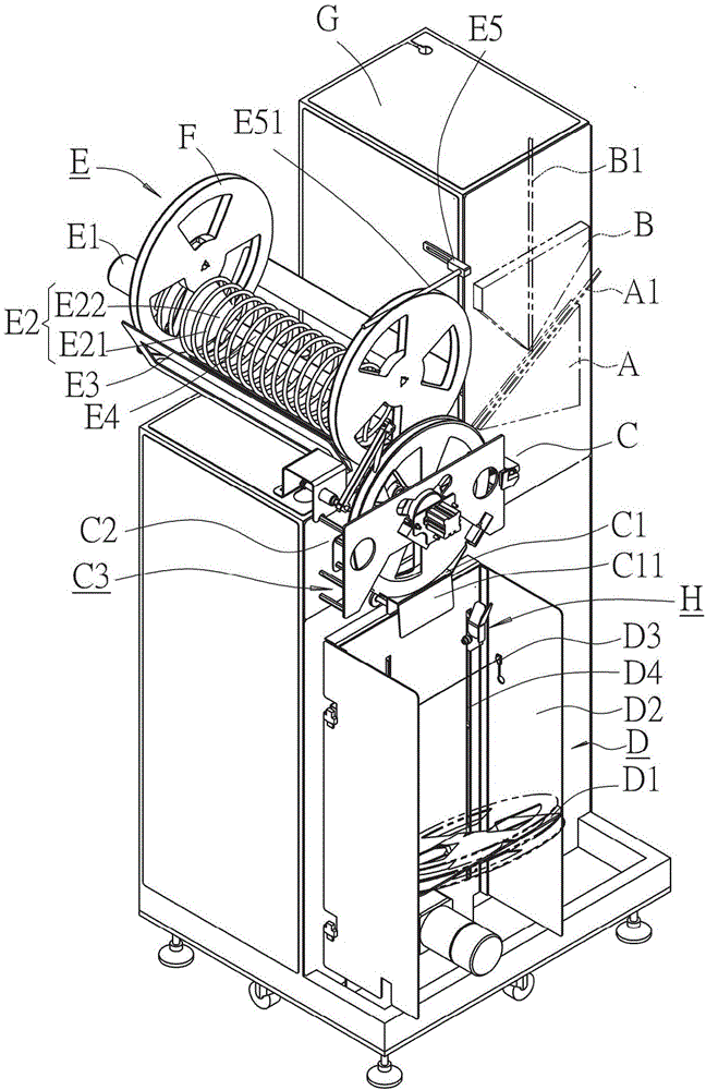
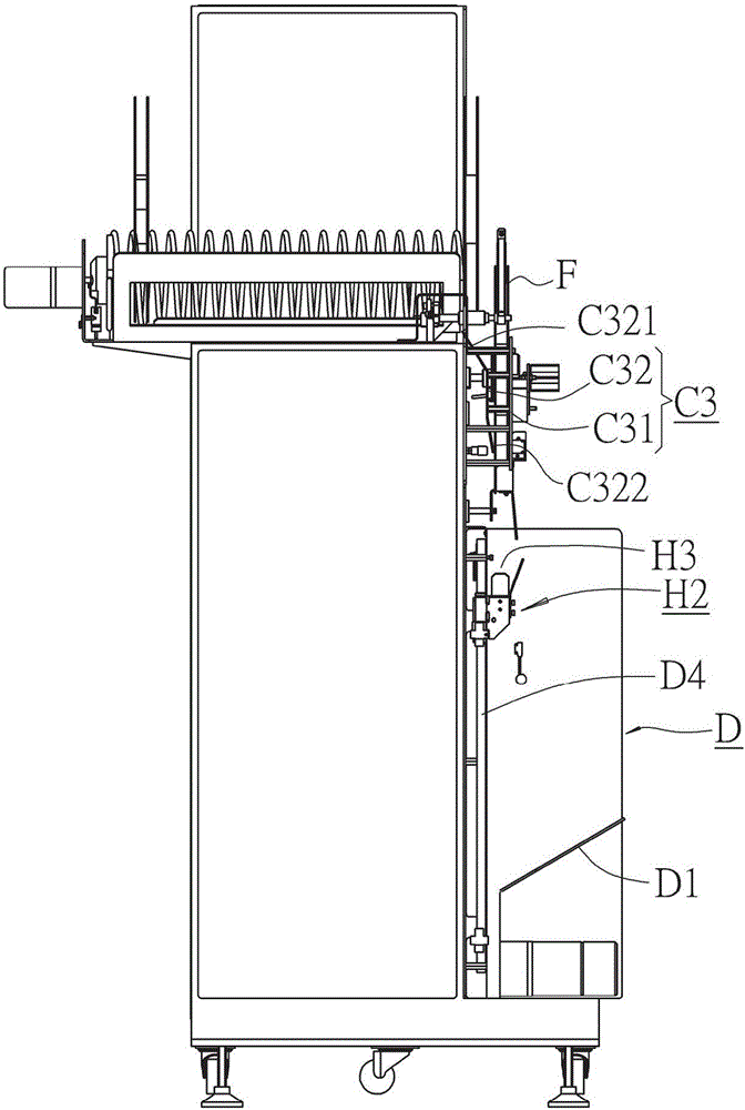
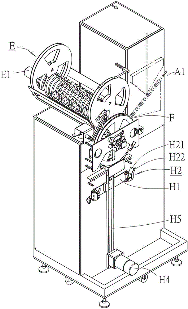
[0039] see figure 1 , 2 , the embodiment of the method and device for conveying the electronic component packaging carrier tape of the present invention can be described with the device shown in the figure, including:

[0040] A carrier tape conveying device A, used to convey the carrier tape A1 that has been placed in the electronic components;

[0041] A sticker conveying device B, used to convey stickers B1;

[0042] A winding device C, which winds up the carrier tape A1 attached to the sticker B1 conveyed by the sticker conveying device B, which includes a bracket C1 that can be driven for forward and backward displacement, and is located above the bracket C1. Provide a carrier C3 with a loading space C2; ​​the bracket C1 is located at the front side with a guide surface C11; the carrier C3 includes a side frame C31 located at the front side of the loading space C2, and behind the rear side of the loading space C2 Side frame C32, wherein, a rearwardly deflected guide po...


PUM


Abstract

The invention provides a roller case conveying method and an apparatus used for an electronic component package conveyor tape The method includes the steps of: successively conveying the to-be-conveyed roller cases into an accomodating space of a first reeling apparatus to reel the conveyor tape by means of a first transmission device; conveying the roller case with the conveyor tape being reeled and moving the roller cases from the accomodating space; transporting the roller cases onto a carriage pallet of a collecting apparatus by means of a second transmission apparatus. The first transmission device is arranged above the reeling apparatus and is provided with case arranging spaces for accomodating the cases; the second transmission device is arranged between the reeling apparatus and a first collection apparautus, and includes a moving carriage bracket which can be driven to move reciprocatingly up-and-down vertically, wherein a pallet space for arranging the roller cases in that the conveyor tapes has been reeled is arranged on the moving carriage bracket. The device saves electricity and power and greatly reduces cost.

Description

technical field [0001] The present invention relates to a conveying method and device, in particular to a method for conveying an empty reel for wrapping up a carrier tape used for electronic component packaging to a location for rewinding the carrier tape, so that the reel that has finished rewinding the carrier tape is conveyed Disclosed are a method and a device for conveying a reel for an electronic component packaging carrier tape to a collecting device. Background technique [0002] Due to the different physical characteristics of general electronic components, they often need to be packaged or classified through the procedures of detection and classification. In the carrier tape of the slot, the carrier tape loaded with electronic components is sent through a take-up device, and the upper opening of the concave carrier tape of the carrier tape is covered with a sticker to cover the opening, and the carrier tape pasted with the sticker is removed. The winding is wound...

Claims


Application Information

Patent Timeline
IPC IPC(8): B65H19/30B65G47/82B65G17/12
CPCB65G17/12B65G47/82B65G2201/0235B65H19/30B65H2301/4181B65H2301/4185
Inventor 黄子展高铭彬
Owner ALL RING TECH CO LTD
Learn More