Rolling and cutting metal plate shearing machine

A roll-cutting, metal plate technology, applied in shearing devices, metal processing equipment, shearing machine equipment, etc., can solve the problems of large system, unstable force, poor section quality of sheared steel plates, etc., and achieve a simple transmission system. Reliable, simplified mechanism, improved quality effect

Active Publication Date: 2007-06-27
TAIYUAN HEAVY IND SCI & TECH +1
View PDF0 Cites 23 Cited by
  • Summary
  • Abstract
  • Description
  • Claims
  • Application Information

AI Technical Summary

Problems solved by technology

They all have some disadvantages. The mechanical transmission type generally has a complex structure and a huge system. The stress on each component of the hydraulic inclined blade shears is not stable enough during the shearing process. Severe warping, poor quality of sheared steel plate section, etc.

Method used


Image

  • Rolling and cutting metal plate shearing machine

Examples


Embodiment Construction

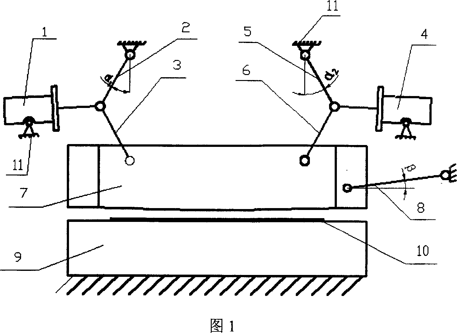
[0014] As shown in Figure 1, the hydraulic cylinders 1 and 4 are installed horizontally and hinged with pins on the frame 11 on the left and right sides above the upper shear blade holder 7, and the ends of the two piston rods pass through the pins. The shafts are respectively hinged with the push rods 2, 5 and the connecting rods 3, 6, and the other ends of the push rods 2, 5 are hinged with the frame 11 through pin shafts, and the included angles with the vertical line are respectively α 1 = -25° and α 2 =25°, the other end of the connecting rod 3,6 is hinged with the upper scissor frame 7 through the pin shaft, one end of the guide rod 8 is hinged with the upper scissor frame 7 through the pin shaft, and the other end is upwardly inclined to the frame 11 are hinged, and the angle with the horizontal line is β=5°. During production, starting the hydraulic cylinders 1 and 4 drives the movement of the connecting rods 3 and 6 and the push rods 2 and 5, which can drive the move...


PUM


Abstract

The present invention belongs to the field of metal plate shearing technology, and is especially hydraulic rolling and cutting metal plate shearing machine. The metal plate shearing machine includes hydraulic cylinders, one transmission mechanism and one shearing mechanism; and features two hydraulic cylinders hinged horizontally on the frame, two piston rods, two link rods, two push rod and the upper shearing edge holder hinged successively, and one guide rod hinged between the upper shearing edge holder and the frame. The present invention has the advantages of simplified mechanism, simple and reliable transmission system and greatly raised sheared section quality.

Description

technical field [0001] The invention belongs to the technical field of metal plate shearing machines, and in particular relates to a hydraulic metal plate shearing machine. Background technique [0002] At present, there are many types of sheet metal rolling shears used at home and abroad, such as double-axis double-eccentric, single-axis double-eccentric, double-axis triple-eccentric, and hydraulic inclined-blade shears. They all have some disadvantages. The mechanical transmission type generally has a complex structure and a huge system. The stress on each component of the hydraulic inclined blade shears is not stable enough during the shearing process. Severe warpage, poor quality of sheared steel plate section, etc. Invention content: [0003] The purpose of the present invention is to provide a new technical solution, which can effectively overcome the defects in the prior art. [0004] The machine structure of the present invention includes a hydraulic cylinder, a ...

Claims


Application Information

Patent Timeline
Patent Type & Authority Applications(China)
IPC IPC(8): B23D15/12B23D15/14B23D15/08
Inventor 黄庆学马立峰张其生冯志军赵春江
Owner TAIYUAN HEAVY IND SCI & TECH
Why Eureka
Try Eureka