Rolling control mechanism for minitype ornithopter

A technology of flapping-wing aircraft and control mechanism, which is applied in the field of rolling control mechanism, can solve problems such as the inability to realize the rolling operation of the flapping-wing aircraft, and achieve the effects of easy operation, strong reliability, and simple mechanism

Inactive Publication Date: 2007-09-26
NORTHWESTERN POLYTECHNICAL UNIV
View PDF0 Cites 25 Cited by
  • Summary
  • Abstract
  • Description
  • Claims
  • Application Information

AI Technical Summary

Problems solved by technology

[0005] In order to overcome the deficiency that the existing technology cannot realize the roll operation of the flapping wing aircraft, the present invent

Method used


Image

  • Rolling control mechanism for minitype ornithopter
  • Rolling control mechanism for minitype ornithopter
  • Rolling control mechanism for minitype ornithopter

Examples


Embodiment Construction

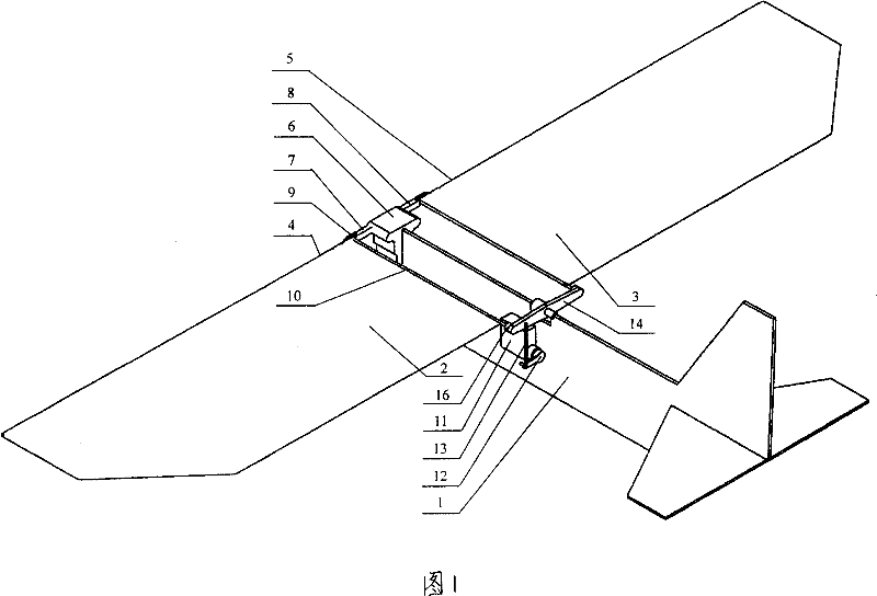
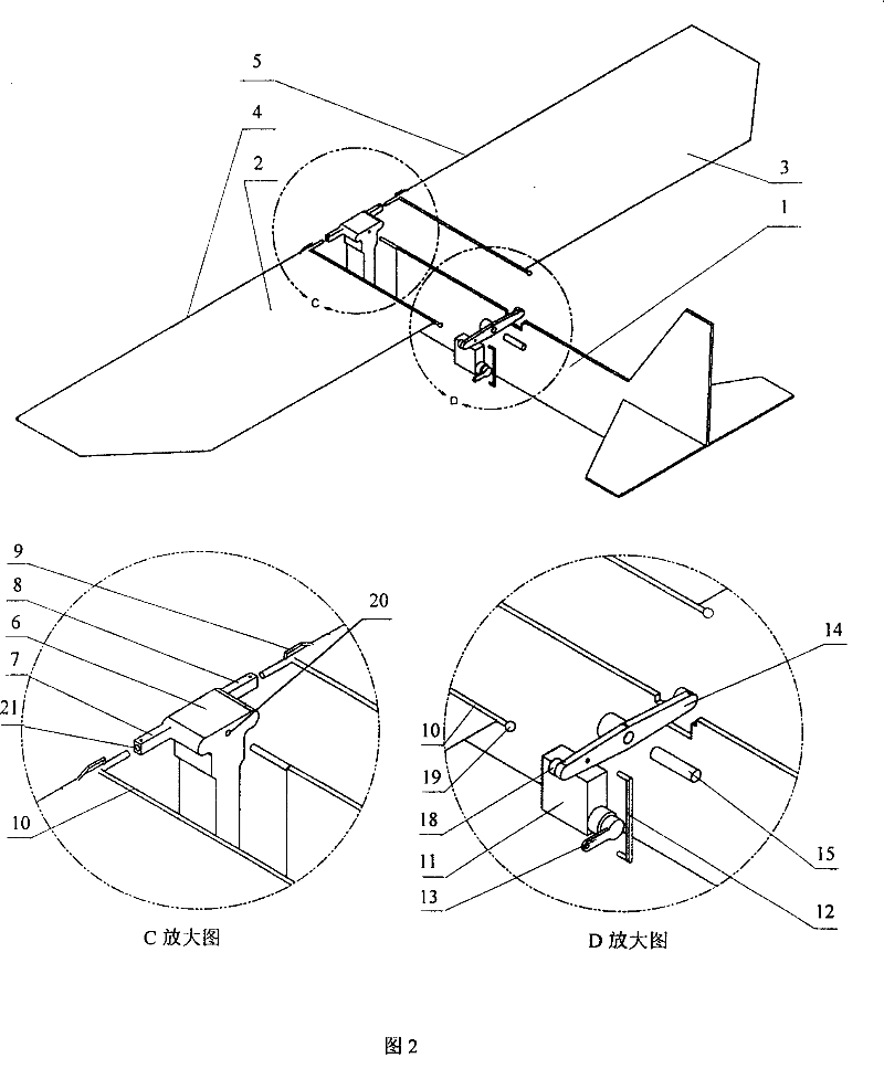
[0019] The present embodiment is a miniature flapping-wing aircraft of conventional layout, comprising fuselage 1, wing, wing flapping mechanism 6, rear bracket 14 and control steering gear 11 in order to support wing. During implementation:

[0020] The flapping mechanism 6 is located at the front end of the fuselage 1, and its upper surface and longitudinal section are T-shaped: a section of cantilever beams protrude from the front end of the upper surface panel to both sides, forming the left rocker arm 7 and right rocker arm of the flapping mechanism. arm 8, and on the end faces of the left rocker arm 7 and the right rocker arm 8, there are inner holes 21 assembled with the front main beam of the wing; font; there is a fuselage mounting hole 20 on the center line of the inner surface of the panel.

[0021] The front end of the fuselage 1 has a mounting pin, by which the front face of the fuselage 1 and the flapping mechanism 6 are fixedly fitted together;

[0022] The wi...


PUM


Abstract

The invention relates to a roll shifting mechanism for micro flapping wing aircraft. In the invention rockers (7, 8) of flapping mechanism (6) are connected with front main beams (4, 5) of wing actively. One end of rib (10) of wings (2, 3) is fixed with front main beams of wing and the other end is connected with back bracket (14) actively through spherical hinge (16). Rockers (7, 8) of control actuator (11) are connected with the back bracket together by pull rod (13) so that a space swinging rod mechanism is constituted by body (1), rockers (7, 8) of flapping mechanism, wings (2, 3) and back bracket (14). When actuator rocker (12) swings to a certain angle, the pull rod (13) drives the back bracket (14) and the rib (10) move correspondingly. Furthermore, wings (2, 3) are driven to carry pitch motion out so that the wing attack angle at one side increases and the wing attack angle at the other side decreases to form lifting difference and generate roll shifting torque. It is provided with simple mechanism, easy operation and strong reliability.

Description

(1) Technical field [0001] The invention relates to a miniature flapping-wing aircraft, in particular to a rolling control mechanism of the miniature flapping-wing aircraft. (2) Background technology [0002] Miniature flapping-wing aircraft is an emerging technical field in recent years. It is usually defined as: the dimension in each direction does not exceed 150mm, and the weight is 10-100g. It has the characteristics of high aerodynamic efficiency, flexible maneuvering, wide application range, and strong concealment when performing tasks, so it has high military and civilian application value. [0003] At present, the elevator and rudder installed at the tail of the aircraft are the most commonly used in the control of the micro-orthopter. The deflection angle of the rudder and the elevator is controlled by the steering gear to realize the turning and pitching of the orthopter. [0004] Since the wings of the existing flapping-wing aircraft flutter up and down during fl...

Claims


Application Information

Patent Timeline
IPC IPC(8): B64C33/02
Inventor 邵立民杨淑利熊超宋笔锋袁昌盛
Owner NORTHWESTERN POLYTECHNICAL UNIV
Why Eureka
Try Eureka