Spherical (spherical surface) mirror surface rolling lathe

A spherical and rolling technology, which is applied in the field of machine tools, can solve problems such as high assembly difficulty, limited precision, and low production efficiency, and achieve the effects of improved production efficiency and quality, high rotary machining accuracy, and simple and convenient maintenance

Active Publication Date: 2010-01-20
宁波市精恒凯翔机械有限公司
View PDF0 Cites 26 Cited by
  • Summary
  • Abstract
  • Description
  • Claims
  • Application Information

AI Technical Summary

Problems solved by technology

[0004] 2. The circular motion of the rotary tool post of this machine tool is driven by a worm gear mechanism, which is complex and bulky
[0005] 3. Mechanisms and systems that do not perform mirror (Ra≤0.1μm) treatment on spherical (spherical) surfaces
[0007] To sum up the above, this kind of machine tool has only one rotary tool post and is driven by a worm gear mechanism. The mechanism is complicated, the manufacturing and assembly are difficult and not conducive to maintenance. The machining accuracy is affected by factors such as component manufacturing and assembly and the power source transmiss

Method used


Image

  • Spherical (spherical surface) mirror surface rolling lathe
  • Spherical (spherical surface) mirror surface rolling lathe
  • Spherical (spherical surface) mirror surface rolling lathe

Examples


Example Embodiment

[0033] The present invention will be further described below in conjunction with the drawings and embodiments.

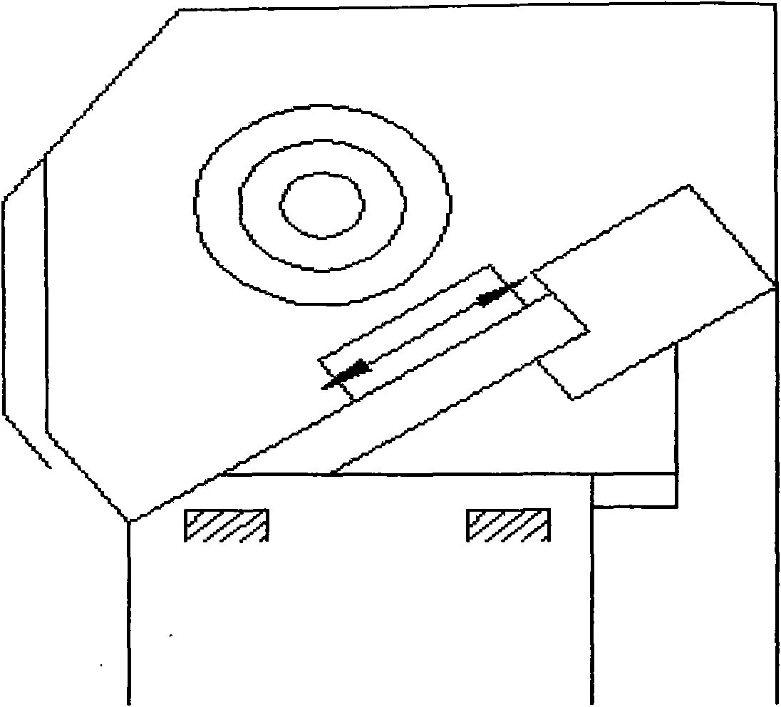
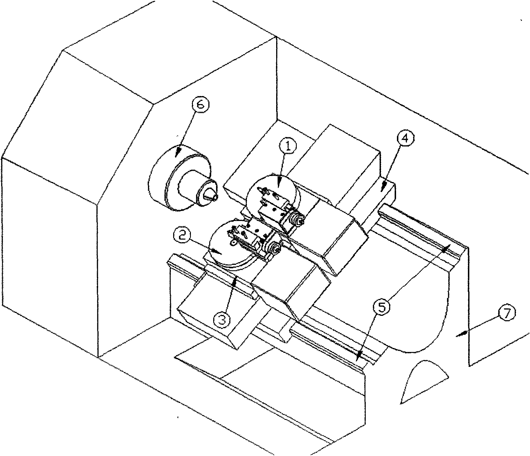
[0034] Such as figure 2 As shown, in the spherical (spherical) mirror rolling lathe of the present invention, there are two mechanisms (1) (2) disc rotary tool post, disc rotary tool which adopts synchronous belt, synchronous wheel and servo motor to drive Inside the rack like image 3 Shown.

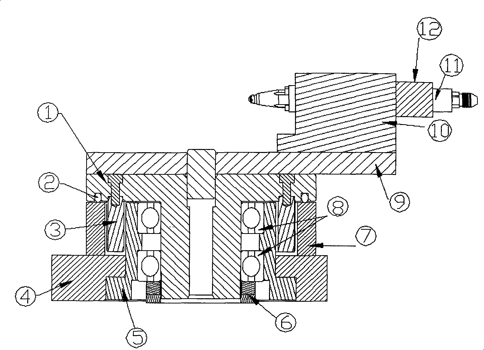
[0035] The power source of the disc rotary tool post is as Figure 5 As shown, (14) servo motor, after receiving the operation command, is transmitted to (3) high-precision disc synchronous wheel through the coaxial (16) servo motor upper synchronous wheel and (13) toothed synchronous belt to drive the disc The moving part of the tool post moves on an arc path around the center of the (8) high-precision large-diameter conical thrust (pressing) bearing, and the moving part of the disc tool post receives the reverse operation command after the servo motor (14) The tool post can mo...


PUM


Abstract

The invention relates to a spherical (spherical surface) mirror surface rolling lathe. A disk revolving tool holder (1) and a disk revolving tool holder (2) which can do circular movement are arranged in the lathe; the disk revolving tool holders are in transmission connection with a servomotor through synchronous belts and synchronous wheels; and a large-diameter thrust bearing (pressure bearing) is used as a tool holder revolving guide rail. The disk revolving tool holder (1) and the disk revolving tool holder (2) are connected with a middle carriage through a disk sealing seat (3), the middle carriage is connected with a large carriage (4) through the guide rail, the large carriage (4) is connected with a guide rail (5), the guide rail (5) is connected with a lathe body (7), and a main shaft (6) is connected with the lathe body (7). One of the tool holders is provided with a special and dismountable cutter system or tool system which is processed by a spherical part surface in a rolling way. The lathe can be used for cutting and processing axisymmetric spherical or externally-forming parabolic parts, and can be used for finely processing the spherical part surface (mirror surface) under the condition that the roughness Ra is smaller than or equal to 0.1 mum. Corresponding devices can be also held on the disk revolving tool holders to develop and upgrade the technologies of drilling, milling, grinding, polishing, quenching and the like, thereby adapting to the processing requirements of spherical (spherical surface) parts in many industries.

Description

Technical field [0001] The invention relates to a machine tool capable of processing spherical (spherical) parts and having a simple structure and easy maintenance. In particular, the invention is a spherical mirror surface machine tool capable of processing the surface of a spherical part to produce a mirror surface (Ra≤0.1 μm) effect. Background technique [0002] At present, machine tools that can process spherical (spherical) have the following characteristics: [0003] First, a rotary tool holder capable of circular motion is installed at the position of the tool holder to form an angle between the workpiece rotation axis and the tool rotation axis, and then process spherical (spherical) parts. [0004] Two, the circular motion of the rotary tool rest of this machine tool is driven by a worm and gear mechanism, and the mechanism is complicated and bulky. There are two kinds of power sources: one is to manually rotate the worm gear for circular motion; the other is to ...

Claims


Application Information

Patent Timeline
IPC IPC(8): B23P23/02B23P9/02B23B5/40B23B17/00B23B21/00B23Q1/01B23Q1/25
Inventor (请求不公开姓名)
Owner 宁波市精恒凯翔机械有限公司
Why Eureka
Try Eureka