Check patentability & draft patents in minutes with Patsnap Eureka AI!

Garbage collection device

A recycling device and garbage technology, applied in garbage collection, garbage cans, household appliances, etc., can solve the problems of urban environmental pollution, unfavorable surrounding environmental health, etc., and achieve the effect of convenient use

Inactive Publication Date: 2019-11-19
朱晨彦
View PDF0 Cites 0 Cited by
  • Summary
  • Abstract
  • Description
  • Claims
  • Application Information

AI Technical Summary

Problems solved by technology

[0002] Garbage disposal has become an important issue in urban development. During garbage disposal, it is necessary to recycle the garbage in the early stage, so that the garbage can be processed in a centralized manner. In the process of garbage recycling, the arbitrary discarding of garbage can be avoided, causing urban environment If it is polluted, a garbage collection device will be used during garbage collection, so that the garbage can be recycled at a fixed point, but a lot of garbage has its own liquid, which will breed smell and attract mosquitoes, which is not conducive to the health of the surrounding environment

Method used


Image

  • Garbage collection device
  • Garbage collection device
  • Garbage collection device

Examples


Embodiment 1

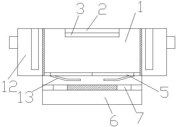
[0016] A garbage recovery device, which is provided with a garbage bin 1, a garbage feeding port 2 is arranged on the upper part of the garbage bin 1, and a cover plate 3 is arranged on the upper end of the garbage feeding port 2, between the garbage bin 1 and the cover plate 3 A drawing groove 4 is provided, and the cover plate 3 is pulled and moved in the drawing groove 4. A sieve plate 5 is arranged at the bottom of the dustbin 1, and a waste liquid box 6 is arranged under the sieve plate 5. The waste liquid box 6 is arranged under the sieve plate 5. A filter sponge 7 is arranged between the liquid box 6 and the sieve plate 5 .

[0017] A warning device 8 is provided on the outside of the dustbin 1 , and the warning device 8 is arranged around both sides of the dustbin 1 .

[0018] The warning device 8 is a warning light, and the warning light is adsorbed on the outside of the dustbin by the suction cup 9 .

[0019] A magnetic suction strip 10 is arranged between the waste...

Embodiment 2

[0021] A garbage recovery device, which is provided with a garbage bin 1, a garbage feeding port 2 is arranged on the upper part of the garbage bin 1, and a cover plate 3 is arranged on the upper end of the garbage feeding port 2, between the garbage bin 1 and the cover plate 3 A drawing groove 4 is provided, and the cover plate 3 is pulled and moved in the drawing groove 4. A sieve plate 5 is arranged at the bottom of the dustbin 1, and a waste liquid box 6 is arranged under the sieve plate 5. The waste liquid box 6 is arranged under the sieve plate 5. A filter sponge 7 is arranged between the liquid box 6 and the sieve plate 5 .

[0022] A warning device 8 is provided on the outside of the dustbin 1 , and the warning device 8 is arranged around both sides of the dustbin 1 .

[0023] The warning device 8 is a warning light, and the warning light is adsorbed on the outside of the dustbin by the suction cup 9 .

[0024] A magnetic suction strip 10 is arranged between the waste...


PUM


Abstract

A garbage collection device is provided with a dustbin. A garbage throwing-in opening is arranged on the upper portion of the dustbin. A cover plate is arranged at the upper end of the garbage throwing-in opening. A drawing trough is arranged between the dustbin and the cover plate. The cover plate moves in the drawing trough in a drawing manner. A screen plate is arranged on the lower portion ofthe dustbin. A waste liquid box is arranged below the screen plate. A filter sponge is arranged between the waste liquid box and the screen plate. The screen plate and the waste liquid box are arranged in the dustbin, solid-liquid separation of garbage can be achieved, a large amount of waste liquid is prevented from being generated in the dustbin, it is guaranteed that the situation that garbagein the dustbin is further rotten to generate a large quantity of foul smells is avoided, the garbage collection device is more convenient to use, and the waste liquid box can carry out concentrated collection treatment on the waste liquid.

Description

technical field [0001] The invention relates to a garbage recovery component, in particular to a garbage recovery device. Background technique [0002] Garbage disposal has become an important issue in urban development. During garbage disposal, it is necessary to recycle the garbage in the early stage, so that the garbage can be processed in a centralized manner. In the process of garbage recycling, the arbitrary discarding of garbage can be avoided, causing urban environment If it is polluted, garbage collection devices will be used during garbage recycling, so that garbage can be recycled at designated locations. However, many garbage has its own liquid, which will breed odor and attract mosquitoes and flies, which is not conducive to the health of the surrounding environment. Contents of the invention [0003] The purpose of the present invention is to provide a kind of garbage recovery device with reasonable structure and waste liquid recovery. [0004] The technical...

Claims


Application Information

Patent Timeline
Patent Type & Authority Applications(China)
IPC IPC(8): B65F1/14B65F1/16
CPCB65F1/14B65F1/1646
Inventor 朱晨彦
Owner 朱晨彦
Features
  • R&D
  • Intellectual Property
  • Life Sciences
  • Materials
  • Tech Scout
  • Unparalleled Data Quality
  • Higher Quality Content
  • 60% Fewer Hallucinations
Learn More