Left-right switching goods taking device for automatic vending machines

A vending machine, left and right technology, applied to instruments, coin-operated equipment for distributing discrete items, coin-operated equipment for distributing discrete items, etc. Cargo door and other issues to achieve the effect of increasing the efficiency of volume use

Inactive Publication Date: 2019-11-19
GUANGDONG DESOUL INTELLIGENT TECH CO LTD
View PDF0 Cites 0 Cited by
  • Summary
  • Abstract
  • Description
  • Claims
  • Application Information

AI Technical Summary

Problems solved by technology

[0002] In the product channel of the vending machine, when the product falls out, it directly falls into the shipping track at the bottom. Due to the high weight of the product itself, when it is necessary to sell some things such as wine bottles, it cannot fall directly, but There is a need for a pick-up pocket that can move freely on the vertical and horizontal planes according to the position and height of the goods, and can catch the goods that will be out of the cabinet. The pick-up pocket can be translated to the corresponding height of the goods, and can not control the delivery channel The goods are moved to the pick-up pocket, and finally the goods are put into the delivery door to solve the technical problem that the goods cannot be smoothly put into the delivery door in the prior art. The present invention is aimed at the delivery channel, the channel The push plate is driven by the driven gear, and the gear is driven by the driving gear in the delivery pocket. When the delivery pocket reaches the delivery channel of the corresponding height, the driving gear in the delivery pocket drives the delivery channel. Driven gear, so as to achieve the purpose of controlling the shipment, but for the goods in the delivery channel located on the inner edge of the vending machine body, due to the limitation of the edge of the pocket itself, a driving gear cannot reach the goods on both sides at the same time. The driven gear, in order to enable the driving gear to reach the driven gears on the left and right sides of the vending machine, it is necessary to switch the left and right pick-up devices in the present invention

Method used


Image

  • Left-right switching goods taking device for automatic vending machines
  • Left-right switching goods taking device for automatic vending machines

Examples


Embodiment Construction

[0013] The present invention will be further described in detail below in conjunction with the embodiments and the accompanying drawings, but the embodiments of the present invention are not limited thereto.

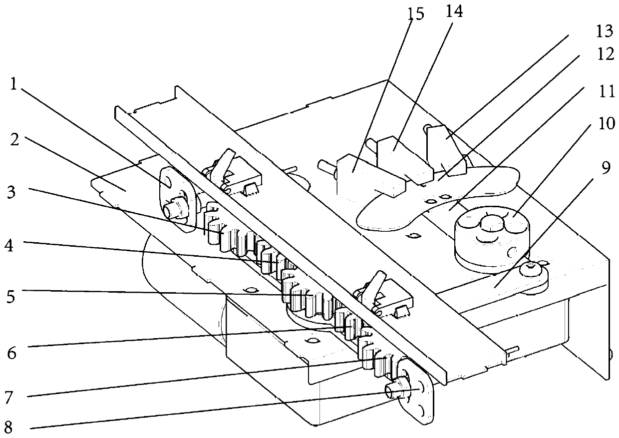
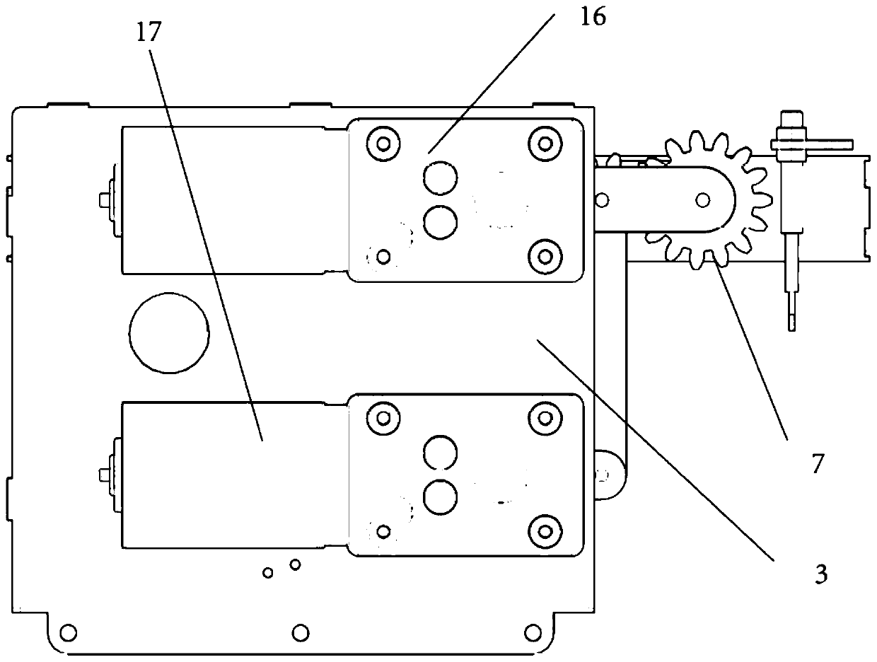
[0014] refer to figure 1 with figure 2 , the left and right switching pick-up device of the automatic vending machine, including the middle plate 2 and installed under the middle plate 2: the first motor 16, the second motor 17, the first articulated rod 11, the second articulated rod 9, the driving gear 6, the first A drive gear 7 and a second drive gear 5, the output shaft of the first motor 16 is connected to a pulsator 10, the pulsator 10 is fixedly connected to the middle part of the first articulated rod 11, when the first motor 16 rotates, the pulsator 10 drives the first articulated rod 11 to rotate, and one end of the first articulated rod 11 is hinged to one end of the second articulated rod 9, and the other end of the second articulated rod 9 is connected to...


PUM


Abstract

The invention discloses a left-right switching goods taking device for automatic vending machines. The device comprises a middle plate, and a first motor, a second motor, a first hinge rod, a second hinge rod, a driving gear, a first drive gear and a second drive gear which are installed below the middle plate. The output shaft of the first motor is connected with an impeller. The impeller is fixedly connected with the middle of the first hinge rod. One end of the first hinge rod is hinged to one end of the second hinge rod. The other end of the second hinge rod is connected with the axis of the driving gear. The output shaft of the second motor is connected with the axis of the second drive gear. The first drive gear, the driving gear and the second drive gear are sequentially connected in a meshed mode, so that driven gears in the goods outlet channels at different positions of the left side, the middle side and the right side can be driven, a push plate can be driven to push goods to fall off, and the goods taking process is completed. The whole device has a simple structure and high practicability.

Description

technical field [0001] The invention relates to the technical field of automatic vending machines, in particular to a left and right switching pick-up device for an automatic vending machine capable of controlling a push plate in a delivery channel. Background technique [0002] In the product channel of the vending machine, when the product falls out, it directly falls into the shipping track at the bottom. Due to the high weight of the product itself, when it is necessary to sell some things such as wine bottles, it cannot fall directly, but There is a need for a pick-up pocket that can move freely on the vertical and horizontal planes according to the position and height of the goods, and can catch the goods that will be out of the cabinet. The pick-up pocket can be translated to the corresponding height of the goods, and can not control the delivery channel The goods are moved to the pick-up pocket, and finally the goods are put into the delivery door to solve the techni...

Claims


Application Information

Patent Timeline
IPC IPC(8): G07F11/16
CPCG07F11/16
Inventor 李军郭帼
Owner GUANGDONG DESOUL INTELLIGENT TECH CO LTD
Why Eureka
Try Eureka