Dielectric cavity dual-bandpass filter

A dual-passband filter, dielectric cavity technology, applied in waveguide-type devices, electrical components, circuits, etc., can solve the problems of inability to freely control the passband bandwidth, unsuitable for mobile communication frequency bands, and large filter loss. The effect of low loss, high volume use efficiency and large power capacity

Inactive Publication Date: 2017-08-04
NANJING UNIV OF AERONAUTICS & ASTRONAUTICS
View PDF3 Cites 11 Cited by
  • Summary
  • Abstract
  • Description
  • Claims
  • Application Information

AI Technical Summary

Problems solved by technology

Among several schemes, schemes based on dual-mode resonators have higher circuit efficiency, but often cannot freely control the bandwidth of each passband
[0004] In terms of implementation form, many current dual-passband filters are in the form of planar circuits, such as microstrip or substrate-integrated waveguide, but the Q value of the resonator is low, resulting in large filter loss.
Although there are a few coaxial cavity dual-passband filter solutions, the resonator Q is often limited to less than three or four thousand in the mobile communication frequency band; and the waveguide dual-passband filter is not suitable for mobile communication frequency bands due to volume reasons (L band and S-band)

Method used


Image

  • Dielectric cavity dual-bandpass filter
  • Dielectric cavity dual-bandpass filter
  • Dielectric cavity dual-bandpass filter

Examples


Embodiment Construction

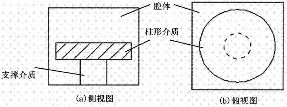
[0022] like figure 1 It is a dielectric cavity resonator loaded with a high dielectric constant cylindrical medium. Among them, a high-dielectric-constant cylindrical medium is loaded in a square metal cavity, and the medium is supported by a low-dielectric-constant cylindrical medium.

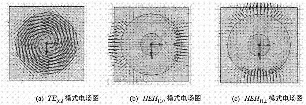
[0023] like figure 2 is the electric field distribution of the main resonance mode of the dielectric cavity resonator. figure 2 (a) shows TE 01δ The electric field of the mode, the electric field rotates around the central axis, and the electric field direction is the φ direction; figure 2 (b) and figure 2 (c) are the two merged HEHs, respectively 11 The electric field of the mode, its electric field polarization direction is parallel to the cross section of the mass, and the electric field polarization direction of one mode is the transverse direction, denoted as HEH 11 / / , the electric field polarization direction of the other mode is the longitudinal direction, denoted as HEH 11⊥...


PUM


Abstract

The invention discloses a dielectric cavity dual-bandpass filter, belonging to the field of filters. A cavity resonator (dielectric cavity resonator) loaded with a high dielectric constant cylindrical dielectric is adopted, two filter pass bands are realized by three of the modes, one filter pass band (signle-die filter) is realized by the TE01 delta resonance mode, and the other filter pass band (double-die filter) is realized by the HEH11 degenerate dual-mode resonant mode. A crotch-shaped probe structure is adopted to realize coupling of the input / output ports to the first and last resonators. A double-probe coupling structure realizes the coupling between two cavities. The coupling between the HEH11 degenerate dual-mode in each cavity is realized by adjusting screws on the cavity diagonal line. The tuning of the modes can be realized by the plurality of adjusting screws arranged on a cover plate. The filter takes full advantage of the lowest three modes of the dielectric cavity resonator to achieve a dual passband filter, thereby being capable of freely setting the center frequency and bandwidth of the two pass bands, and having the advantages of low loss, small size and large power capacity.

Description

technical field [0001] The invention relates to the field of dielectric cavity double passband filters. Background technique [0002] With the continuous emergence of various communication standards, multi-frequency and multi-mode RF front-ends have become a development trend. In order to construct these RF front-ends, dual-pass or multi-pass filters are required. [0003] The currently published dual-passband filter design schemes are roughly as follows: the first scheme is to use two single-passband filters in parallel, each filter generates a passband, thereby obtaining two passbands; One scheme is to use a broadband band-pass filter and a band-stop filter in series, use the stop-band of the band-stop filter to split the passband of the band-pass filter, and divide it into two to obtain two passbands; the third scheme is to use The band-stop resonator unit is embedded in the band-pass filter, so that the pass-band is split into two; the fourth scheme is a dual-mode reson...

Claims


Application Information

Patent Timeline
Patent Type & Authority Applications(China)
IPC IPC(8): H01P1/207
CPCH01P1/207
Inventor 刘云蒋帅
Owner NANJING UNIV OF AERONAUTICS & ASTRONAUTICS
Why Eureka
Try Eureka